Continue to Site

Welcome to EDAboard.com

Welcome to our site! EDAboard.com is an international Electronics Discussion Forum focused on EDA software, circuits, schematics, books, theory, papers, asic, pld, 8051, DSP, Network, RF, Analog Design, PCB, Service Manuals... and a whole lot more! To participate you need to register. Registration is free. Click here to register now.

Design of equivalent circuit for HJFET NE3509M04

Status
Not open for further replies.

ashishchandra

Junior Member level 2
Joined
Jun 9, 2009
Messages
23
Helped
5
Reputation
10
Reaction score
4
Trophy points
1,283
Location
India
Activity points
1,460
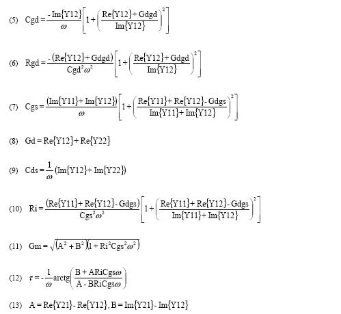
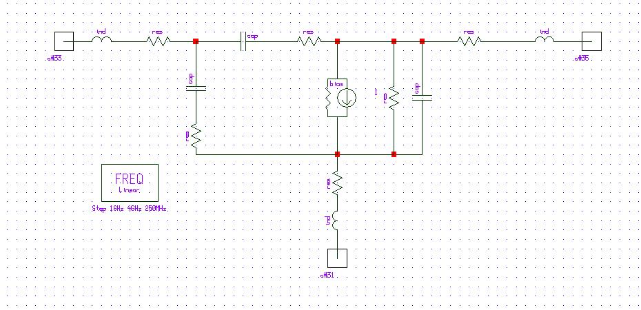
I m 2nd yr Btech student and i m working on a project to find the equivalent structure for NE3509M04 using the software packages ADS or serenade.Here the image for the general equivalent circuit for HJFET


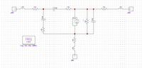
My problem is how to find the values for resistances,inductances in the given circuit using the data sheet(s-parameter) and above software packages.i m attaching the data sheet for refernce Please help me in this area.......
 

You need pulsed S parameters, the datasheet = cw S parameters. Model parameters extraction is performed with pulsed IV/S measurement.
 

i dont get it what u wanna tell. my guide told me to make the structure of above HJFET using the datasheet he provided.
i already know a method to fond out the values of above resistances and inductances in above figure but the problem is they require about 1000 calculations...
so my problem is how to find the values of passive components in above circuit which gives the same s-parameter values as provided in datasheet.....
 

you want to extract a small signal model of this device. But the datasheet provides S parameters measurement in continuous mode. Extraction of transistor model is done with pulsed measurement, because you have to avoid thermal effect.

The model obtained will be significantly different. It's not easy to create a transistor model.

I give you some equations maybe it could help you:

40_1244796037.jpg
 

Hi all,

Jayce is right, so you need to measure your transistor for diffrent polarization point such as for Vds=0V and for threshold voltages so the s parametres in datasheet are not sufficent for making a model.

i ahve a question to jayce3390:

pls where you have found the diffrent expression for JFET model ?

what about from equation (1) to (4) ?


thank
 

These equations are usually used to extract the model, I don't remember where I found but I am sure you will find in every specific books.
1 to 4 is not related to the model.
 

oki, thank you so much.......

Added after 23 minutes:

Dear jayce3390,

And what about the noise Model ?

I think the cicruit is similar but the components are related to Ta: Ambiant temperature.

Do you have an idea about it ?

Thank you in advance,
 

Yes, the small signal model extraction is done at ambient temperature. I have no idea about noise, because model I do it's only power device, I don't care about the noise parameter.
 

Status
Not open for further replies.

Part and Inventory Search

Welcome to EDABoard.com

Sponsor

Back
Top