Continue to Site

Welcome to EDAboard.com

Welcome to our site! EDAboard.com is an international Electronics Discussion Forum focused on EDA software, circuits, schematics, books, theory, papers, asic, pld, 8051, DSP, Network, RF, Analog Design, PCB, Service Manuals... and a whole lot more! To participate you need to register. Registration is free. Click here to register now.

How to generate rectangular pulse with fall time about 200ps

Status
Not open for further replies.

05031208

Newbie level 3
Joined
May 31, 2009
Messages
4
Helped
0
Reputation
0
Reaction score
0
Trophy points
1,281
Activity points
1,312
avalanche transistor pulse generator

I want to generate a rectangular pulse with width adjustable from 1ns to 10ns.
It's fall time should be about 200ps.
The amplitude of the pulse is about 8v to 10v.

How can I make them ?
Thaks you all!
 

hp an918

You may want to tell about the intended voltage range and also the diode type used in your circuit.
Delay line avalanche transistor generator, as suggested by AN94, has the drawback of a fixed pulse width and is
limited to about 350 ps rise- and fall time according to my experience.
 

    05031208

    Points: 2
    Helpful Answer Positive Rating
rectangular pulse

Part of the problem will be to accurately measure this. Will require at least a 2GHz or more sampling scope.
 

pulse generator

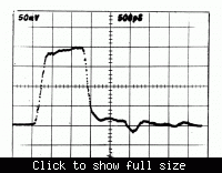
Yes, that's right. I have to correct my above statement regarding avalanche rise-/fall-times. I see, that I achieved about 150 ps with a 20V pulse generator (selected 2N708 transistor), recorded with an old Tektronix sampling scope.


I assume, that you've been using a step-recovery diode. Can you specify the type?
 

how to generate a pulse input

FvM said:
You may want to tell about the intended voltage range and also the diode type used in your circuit.
Delay line avalanche transistor generator, as suggested by AN94, has the drawback of a fixed pulse width and is
limited to about 350 ps rise- and fall time according to my experience.


You are right that delay line avalanche transistor generator has the drawback of a fixed pulse width and is limited to about 350 ps rise- and fall time.
The amplitude of the pulse is about 8v to 10v,the diode model I used is MMD820-E28 from Metelics Corp.
Thank you for your attention!
 

what is the time period of rectangular pulse

These diode pulse shaping methods are good for generating an impulse, but not so good for generating a long (10 ns) pulse.

What about just feeding a flip flop with a variable sine wave frequency, like a SY5585u, you set on the rising edge of the sine wave input as the CLK input, and reset on the falling edge. You can amplify using a broadband or dc coupled amplifier to get the amplitude you need.
 

generating a sinewave from a pulse

biff44 said:
These diode pulse shaping methods are good for generating an impulse, but not so good for generating a long (10 ns) pulse.

What about just feeding a flip flop with a variable sine wave frequency, like a SY5585u, you set on the rising edge of the sine wave input as the CLK input, and reset on the falling edge. You can amplify using a broadband or dc coupled amplifier to get the amplitude you need.

Thank you for your help!
But how can i make the fall time 200ps?
 

rectangular pulse of time t

That is the question (not easy) and why you pay many $$$'s for good pulse generators. My Agilent 33220A cost almost $2k and rise times of only 5nS. The faster ones are about 5-10 times more to get 200pS

Performance Characteristics of the 8133A
Form Factor Benchtop
Type Other
Number of Channels 6 ch
Maximum Frequency 3.0 GHz
Frequency Accuracy 0.1 %
Minimum Pulse Width 150 ps
Maximum Pulse Width 10 ns
Maximum Output Voltage 3 V
Minimum Period 300 ps
Maximum Period 30 ns
Minimum Delay 0.000 ns
Maximum Delay 10 ns
Output Impedance 50 Ohm
 

fast rise fall time pulse

I might be tempted to design it with this laser driver:

**broken link removed**


In place of the laser diode and Rser I would have the resistive load.

I would drive the input differential Din with a small sine wave at 50 MHz. I would use a fixed DC voltage on notDin, and vary it so the ecl input gate was a comparator. Then varying the DC voltage should get me 1 to 10 nS pulse width. Rise fall times look like 100 ps.

You could screw with the enable pin if you wanted only a one-shot.

Would run the whole thing at 6 V supply.

Probably get something like a 4V output. Then would amplify if higer needed, or maybe use 2 of them in push pull tandem thru a balun. If you could find a big enough bandwidth transformer, the chip will put out 30 mA, so you could get your voltage with a step up transformer.
 

fall time for 2n2222

A short summary of the HP step recovery applications note could go like that: You can achieve a lot of really fast waveforms, but hardly a rectangular pulse...

I basically share biff44's opinion, that a fast transistor switch, e.g. the said laser pulser, is a promising solution. The required 8-10 V however are restricting the available transistor choice, so it would be much easier, if it could be reduced. Also all state-of-the-art commercial pulse generators, as the 8133A mentioned by E-design, are operating in a restricted voltage range.

I also miss a specification of the intended analog pulse quality. From the initial post, I'm under the impression, that a few percent deviation is already too bad. I fear, this kind of specification can turn the project easily into fiction.
 

agilent 33220a how to compute rise fall time

FvM said:
A short summary of the HP step recovery applications note could go like that: You can achieve a lot of really fast waveforms, but hardly a rectangular pulse...

I basically share biff44's opinion, that a fast transistor switch, e.g. the said laser pulser, is a promising solution. The required 8-10 V however are restricting the available transistor choice, so it would be much easier, if it could be reduced. Also all state-of-the-art commercial pulse generators, as the 8133A mentioned by E-design, are operating in a restricted voltage range.

I also miss a specification of the intended analog pulse quality. From the initial post, I'm under the impression, that a few percent deviation is already too bad. I fear, this kind of specification can turn the project easily into fiction.

Thanks for your help! Appreciating for your help!
Anticipating for more advice!!!!
 

Status
Not open for further replies.

Part and Inventory Search

Welcome to EDABoard.com

Sponsor

Back
Top