Continue to Site

Welcome to EDAboard.com

Welcome to our site! EDAboard.com is an international Electronics Discussion Forum focused on EDA software, circuits, schematics, books, theory, papers, asic, pld, 8051, DSP, Network, RF, Analog Design, PCB, Service Manuals... and a whole lot more! To participate you need to register. Registration is free. Click here to register now.

Active Front End Converter?

Status
Not open for further replies.

stevendhansen

Newbie level 3
Joined
May 21, 2009
Messages
3
Helped
0
Reputation
0
Reaction score
0
Trophy points
1,281
Activity points
1,313
active front end

Hey guys...new poster here. I'm currently developing an active front end converter and I have some good ideas on how to design the power side, but I'm not sure about the controller. I am fairly new to this kind of design, but I have worked with active converters for years...

How is the controller typically implemented for active front end control? I would like to design a PID controller using an outer voltage loop and an inner current loop. If anyone has a block diagram, that would be perfect!

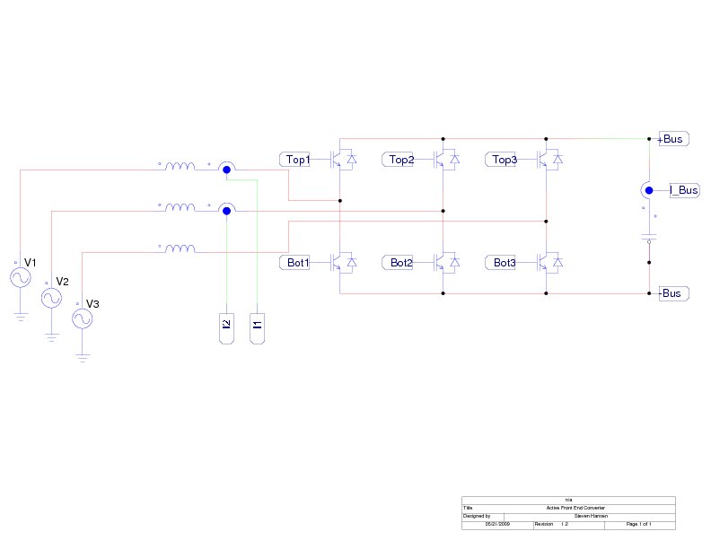
I have attached a my basic power schematic...


V1, V2, and V3 refer to the 3 phase line voltage.

Any thoughts?
 

active front end converter

Hi there, not sure if you are still looking for a reply as the post is fairly old.

Firstly are you looking at an analog solution or a DSP solution?

There are several ways the control system can be implemented but I will outline the basics of the more common methods.

The outer PI loop works on the voltage error to give a current command. At this stage forward compensation for load current can be implemented by using an extra PI loop to look at the error between the current command and the load current. The final current command is then multiplied by each of the phase voltages to give the desired phase current. Each phase then has a current control PI loop which works on the error between the desired and actual phase current to generate a PWM command to control the half bridge for that phase.

Another method that is popular with DSPs is very similar to the above but utilises park and clark transforms and their inverse transforms to minimise the number of PI loops required. Only one current control PI controller required instead of 3.

From memory TI had an example application for one of their TMS320F28xx series evaluation boards.
 

front end converter

Thanks for the feedback...this is exactly what I have been looking for. BTW I am designing a digital control system.

My DSP as of today is a Delta Tau Turbo PMAC2, but I am planning on moving to a custom DSP made by a private company that designed their DSP specifically to control missle positioning systems for the military.

Are there any documents or websites that give a good explanation of the clarke/park transforms as used in a Chopper or Active Front End? I understand how to use clarke/park transformers, but personally I have only used them to control induction machines via pwm inverters.

I have heard that using clarke / park transforms in your control loop allows direct Id and Iq control. What I am really looking for is a controller that contains an outer voltage loop, an inner current loop, plus angle control.

Thanks!
 

active front end

I understand how to use clarke/park transformers, but personally I have only used them to control induction machines via pwm inverters.
In my opinion, the operation is similar in many aspects. AFE control can also use two phase orthogonal (Iα, Iβ, Vα, Vβ) space vector descriptions. As a specific point, a mains frequency sinusoidal model current has to be generated somehow, typically by a filter or a PLL. The outer loop controller output is multiplied with the model current to generate the inner loop setpoints. In addition a voltage feedforward and possibly compensation of inductance voltage drop can improve the behaviour. A two phase voltage measurement is required for model current generation and voltage feedforward.
 

active front end filter

Hi Steven,

I begin to design a AFE for my wind application system. The main research point of my work is to design a cascade mutli level inverter. I try to simulate it via MATLAB/SIMULINK.

Could you please help me designing in AFE?! An easy example or the documentation that you used before.

Normally, IGBTS are used in AFE but I want to realize it with the help of MOSFETs.
regards
 

can u please send me some reference for active rectifier where i can get algorithm details/
 

Status
Not open for further replies.

Similar threads

Part and Inventory Search

Welcome to EDABoard.com

Sponsor

Back
Top