Fragrance
Advanced Member level 4
- Joined
- Jul 26, 2002
- Messages
- 1,190
- Helped
- 248
- Reputation
- 496
- Reaction score
- 202
- Trophy points
- 1,343
- Location
- East Of Earth
- Activity points
- 8,933
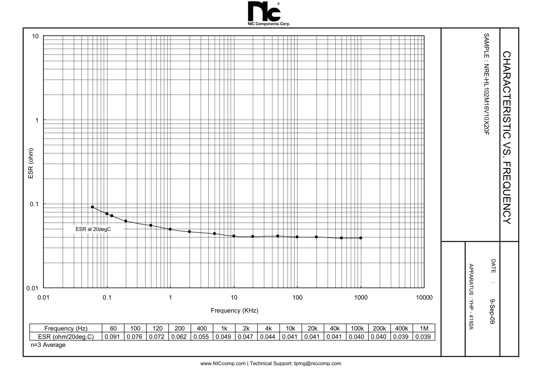
pic esr meter
Dear all,
here is nice project a pic based ESR meter
**broken link removed**
Regards
Fragrance
Dear all,
here is nice project a pic based ESR meter
**broken link removed**
Regards
Fragrance