Continue to Site

Welcome to EDAboard.com

Welcome to our site! EDAboard.com is an international Electronics Discussion Forum focused on EDA software, circuits, schematics, books, theory, papers, asic, pld, 8051, DSP, Network, RF, Analog Design, PCB, Service Manuals... and a whole lot more! To participate you need to register. Registration is free. Click here to register now.

Circuit designed for Slew Rate problem

Status
Not open for further replies.

Monady

Advanced Member level 4
Joined
Dec 1, 2008
Messages
109
Helped
12
Reputation
24
Reaction score
3
Trophy points
1,298
Activity points
2,151
SR Problem

Hi dear all friends
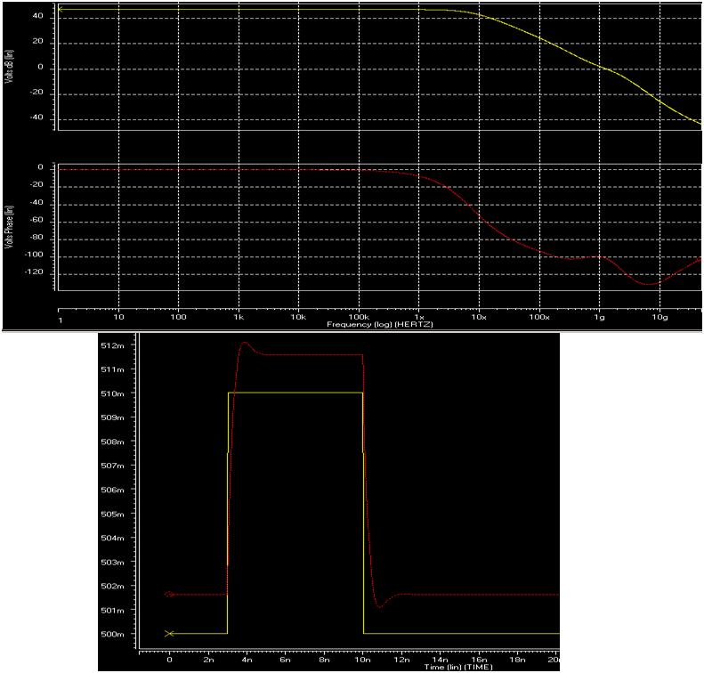
I used of folded cascode opamp as unity gain buffer, this circuit designed for Slew Rate greater than 2.5*10^9 V/S (due to the 0.5V variation in 0.2ns). after simulation, I(M11) was 1mA with 0.3pF capacitance load, and it means: SR=1mA/0.3pF= 3.33*10^9 V/S. I really mixed up because as you can see in the attached pic, output settle in more than 2ns although SR is reasonable .
I would be appreciated for any help.
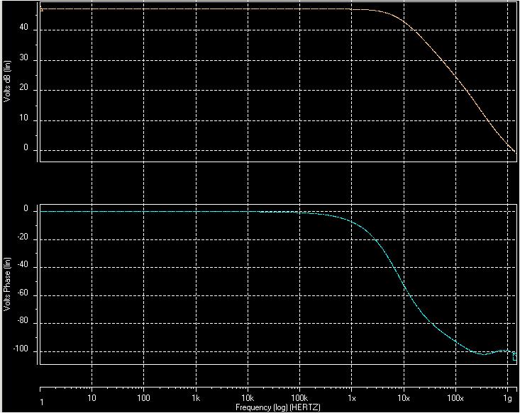
P.s.:eek:pen loop UGBW is higher than 1GHz, Phase margin=80degree
 

SR Problem

Don't you need a higher BW then? I believe you would need at least 5GHz.
 

Re: SR Problem

Phase margin does not look like 80deg., did you account for the load during that sim?
 

SR Problem

Thx for your replies,
Dear JoannesPaulus, if open loop UGB=1GHz then closed loop W-3dB will be B*UGB=UGB=1GHz(B=1 because of unity gain feedback). thus i think this value is sufficient.
Dear saro_k_82, yeah i'm sure about it.open loop freq. response attached.
 

Re: SR Problem

OK, first of all, for your calculations as well as for your simulations you have to include the parasitic capacitances. You have it in unity gain, so at the output node you have 300fF+gate capacitance of M2+drain (or source) parasitic cap of M4 and M8, make sure you include that in your calculations.

Also, when you open the loop to do the ac analysis, make sure that you include at least the gate cap of M2 so your bandwidth is realistic.

Keep in mind that 300fF is not too much, if M1 & M2 are large, they could be significant
 

    Monady

    Points: 2
    Helpful Answer Positive Rating
Re: SR Problem

It will be interesting to see what happens after 1GHz., (multiple crossovers, sharp phase transitions etc..) Clearly a system with 80deg phase margin cant even overshoot.., let alone the ringing it displays. A transient response truly indicates the stability of the system., just check how the system behaves for very small steps inputs (of the order of 10mV) If it is the same, the obtained bode plot must be suspected.
 

SR Problem

Wow!you're right, i didn't consider parasitic cap in my calculation. parasitic caps are about 250fF.I know that 0.3pF for compensation load is so small but because i'm working on high speed circuits thus if i double this cap thus i have to double tail current too in order to preserve previous slew rate. thus what can i do without consuming more power?

dear saro_k_82, you're right that 80degree PM can't overshoot and due to it i confused.
 

Status
Not open for further replies.

Part and Inventory Search

Welcome to EDABoard.com

Sponsor

Back
Top