Continue to Site

Welcome to EDAboard.com

Welcome to our site! EDAboard.com is an international Electronics Discussion Forum focused on EDA software, circuits, schematics, books, theory, papers, asic, pld, 8051, DSP, Network, RF, Analog Design, PCB, Service Manuals... and a whole lot more! To participate you need to register. Registration is free. Click here to register now.

IGBT Driver - Active Clamp

Status
Not open for further replies.

berni80

Member level 2
Joined
Jun 28, 2008
Messages
47
Helped
1
Reputation
2
Reaction score
1
Trophy points
1,288
Activity points
1,627
active clamping

Hi,

has anyone an experience with the active clamp on IGBT driver?

I'm using an IGBT IC driver without it, but I would like to add this feature
with some external components.

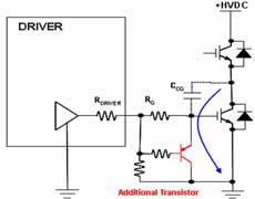
I find this topology (see below) but I'm not so convinced because it isn't really "active".
It is just like to have different Rgate for ON and OFF (with Rgate OFF approximately zero). The gate charge through Rg and discharge through red transistor.

33_1238436801.jpg


More useful is a driver like the ST TD350 or the AVAGO ACPL-332J.

Here the DSs:
https://www.st.com/stonline/products/literature/ds/9525/td350.pdf


The clamp is active only when the IGBT OFF transient is finished and it doesn't affect the OFF switching phase.

Could you suggest me some circuit to implement it or some doc to refer to?

Thanks


[/url]
 

igbt driver

The shown circuit isn't implementing active clamping at all. Active clamping with IGBT is basically similar to active clamping as realized by an internal Z-Diode between drain and gate in some self-protecting MOSFET devices. It's purpose is overvoltage protection. Because of the much lower driver impedance, active clamping with IGBTs usually involves the driver, too. I attach the external circuitry suggested for active clamping with an Eupec/Infineon IGBT driver module. The said sense pin is the base node of the push-pull common collector driver transistors (also designated totem-pole driver).

P.S.: The remark not yet tested with all IGBT modules! should be understood as a serious warning. It's not said, that a means as active clamping, intended as a protection always works as expected. It may also cause parasitic oscillations and at worst case catastrophic failure of the device in some cases.

I also attached a paper discussing some protection techniques.
 

active clamp

Thanks for the info.

But I think we have to divide the "active clamp" into two categories:

One is the gate active clamp to minimize the Miller capacitance effect at turn off.
The aim of this is to guarantee the OFF phase.

Another is the voltage clamp.
The aim of this is to limit the over-voltage during switching.

I was asking about the first, here some more details:
 

active miller clamp

Of course the Agilent/Avagotech guys are free to use the term active clamp at will. It think, it's misleading, cause it has been used in the other way since long. But no problem.

Generally, the Avagotech driver is facing the parasitic turn-on problem, cause they try to safe a negative supply. The solution may be meaningful in low power/low cost IGBT applications. Considering state-of-the art in power electronics, it looks like a poor-mans gate driver.

The active point is using an active device, a BJT with a current gain. Although it's somewhat limited, it serves it's purpose. One may wonder, why the same function can't be implemented inside the driver itself?
 

miller clamp

FvM said:
Considering state-of-the art in power electronics, it looks like a poor-mans gate driver.

I know that is quite usual to have a negative supply, but, in any case, this kind of
clamp can increase noise immunity.

Also ST follows this trend.

FvM said:
One may wonder, why the same function can't be implemented inside the driver itself?

Avago has driver with the clamp integrated but it is more smart than the external BJT solution. The clamp is activated only after the OFF switching phase, monitoring the
Vge.

I think isn't too easy to add this function (with ext. components) to a driver without it.
 

igbt driver datasheet

I totally agree with Berni80. He cleverly indicated two different usage term of active miller clamp. In drivers the problem is current itself due to miller capacitance. Resulted voltage drop on gate resistance can be turning on the IGBT, when it reaches to certain level (depends on IGBT).

332J has internal dedicated active circuitry with low impedance to clamp this current away before it flows through gate resistor. Berni80's external clamp is another way, but as far as I understand there is no Vge monitoring as 332J has (for comparison I refer to the paper also).

FvM wrote:

Generally, the Avagotech driver is facing the parasitic turn-on problem, cause they try to safe a negative supply. The solution may be meaningful in low power/low cost IGBT applications. Considering state-of-the art in power electronics, it looks like a poor-mans gate driver.

This sounds little bit argument of sales rather than technical. :D Sure internal clamp should have/has limitation. I checked the datasheet and it was there. The sinking current is typically ~1.1A, max 1.7A. I interpret this it is proper for applications around this level. The part is not for direct miller coupling currents of 10A with 6.5kV/1000A "state-of-art" IGBTs. In such a case, as per datasheet, you need external buffers and clamp is not used. It is clear.

By the way, parasitic turn-on possibility due to miller coupling is concern for many drivers, not only for certain parts. because it is also Rg dependent. This is why normally there is a negative gate voltage recommended by many suppliers, including Infineon itself.
 

igbt driver module

The part is not for direct miller coupling currents of 10A with 6.5kV/1000A "state-of-art" IGBTs. In such a case, as per datasheet, you need external buffers and clamp is not used. It is clear.

I don't see, that the part is a good candidate for high power IGBT applications, mainly because the insulation voltage and particularly overvoltage category is far from meeting professional requirements. Also, unlike other IC drivers, it don't seem to be specially designed for bipolar gate drive, e.g. with the shield referenced to Vee.

I agree with the conclusion, that external boost transistors and bipolar supply would be used in high power applications. The question is, if the said "active clamp" would be still needed then. The Avagotech data sheet is also suggesting a bipolar drive, external driver variant with additional clamp. But I don't think that it would be needed at all, because the positive and negative gate current is in a similar order of magnitude as expectable miller currents.

I think, the main purpose of an additional active clamp option is for applications with bad switching behaviour, where the gate drive must be slowed down to protect IGBT and diodes from inductive overvoltages. In this case, a hard pull down or "clamp" that is activated after switch-off can be meaningful.
 

igbt active clamping

@ FvM
I respect your thoughts, even though I don't agree on some points :)

The document you attached before is interesting,. Is it fully available?

Cheers
 

negative supply igbt driver

Which document do you mean? The Eupec paper has been send to my by an Eupec application engineer. The schematic is from the Eupec driver datasheet
**broken link removed**
 
  • Like
Reactions: Nafic

    Nafic

    Points: 2
    Helpful Answer Positive Rating
voltage clamp igbt

Yes I meant this. Thanks.
 
  • Like
Reactions: Nafic

    Nafic

    Points: 2
    Helpful Answer Positive Rating
All of these are very usefull. thanks a lot.
 

Status
Not open for further replies.

Similar threads

Part and Inventory Search

Welcome to EDABoard.com

Sponsor

Back
Top