CQCQ
Member level 3
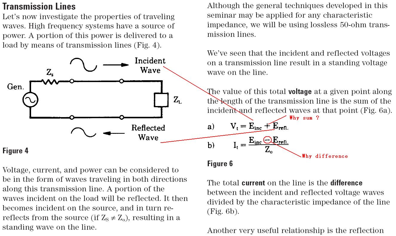
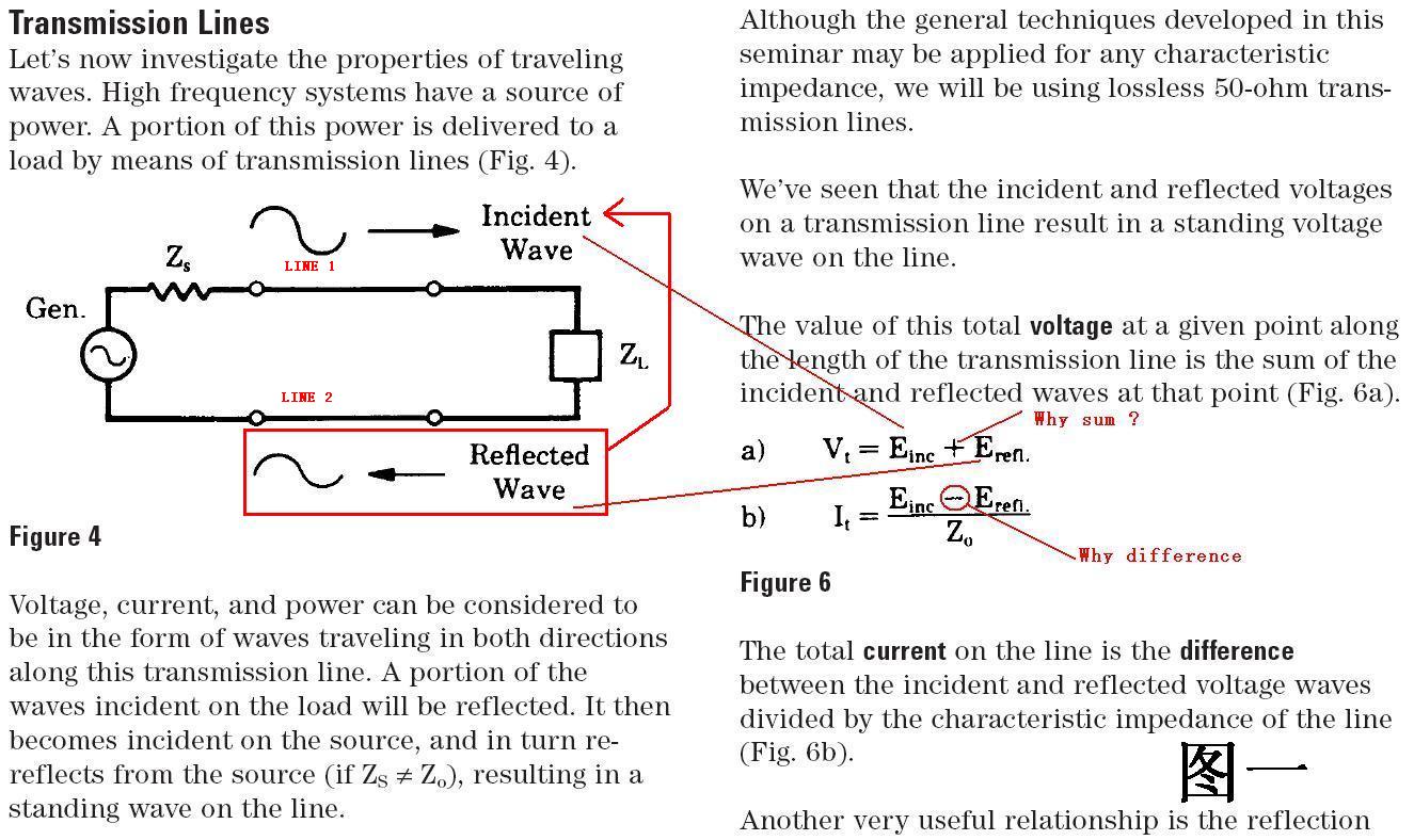
reflections in transmission lines
Hi! I have some basic problems need help ...
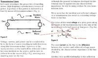
plz see the picture, I dont know why the "V total" equ E inc + E refl ,"I total" equ I inc -I refl ?
Any good paper or something can help me understand this problems?
Thanks in Adnance!
-cqcq
Hi! I have some basic problems need help ...
plz see the picture, I dont know why the "V total" equ E inc + E refl ,"I total" equ I inc -I refl ?
Any good paper or something can help me understand this problems?
Thanks in Adnance!
-cqcq