Continue to Site

Welcome to EDAboard.com

Welcome to our site! EDAboard.com is an international Electronics Discussion Forum focused on EDA software, circuits, schematics, books, theory, papers, asic, pld, 8051, DSP, Network, RF, Analog Design, PCB, Service Manuals... and a whole lot more! To participate you need to register. Registration is free. Click here to register now.

Isolated Feedback for Flyback

Status
Not open for further replies.

berni80

Member level 2
Joined
Jun 28, 2008
Messages
47
Helped
1
Reputation
2
Reaction score
1
Trophy points
1,288
Activity points
1,627
isolated feedback

Hi,

I would like to have you opinion on this simple topology (see the attached image) to
get an isolated feedback from the secondary of a flyback.

Does this circuit work?

I think the CTR of the opto has a big influence on the regulated supply.
Is it true?

Could you suggest me the simple way to get an isolated feedback?

Thanks!!
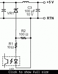
 

flyback feedback

Variable reference voltage/shunt regulator ICs as TL431 or LM385-ADJ are often used in commercial products and suggested in application circuits. You'll find many references at EDAboard.
 

isolated feedback

FvM said:
ICs as TL431 or LM385-ADJ

I saw a lot of circuit that use these ICs, but which kind of advantage give these ICs?
Compared to the solution I propose.. does it work?

I would like to avoid an ICs on the isolated side, for space needs.
 

flyback with primary side feedback

If you don't need exact regulation and can accept the temperature drift introduced by the optocoupler, your circuit can be used.

I don't think, that the shown pin assignment meets any usual opto coupler, B.T.W. They would require to left pin 6 unconnected.
 

feedback control loop + flyback

Thanks for your reply.

The opto with this pinout is the ACPL-M43T by Avago.

Here the datasheet:
https://media.digikey.com/pdf/Data Sheets/Avago PDFs/ACPL-M43T.pdf

I do not need a good regulation, but I'm worried about the Current Transfer
Ratio (CTR). It has a typycal value of 45, but can vary form 32 to 80.

Does the CTR influence the regulated voltage??!
Or it is compensate in some way by the control loop?
 

flyback isolated feedback tl431

I try to better explain my doubts..

With some approximation, in steady state:

CTR = Ir1 / Ir2 = Vout/R1 * R2 / Vfb

Vout = Regulated Voltage
Vfb = Voltage feedback usad by the swithcing IC
Ir1 = current flowing into R1
Ir2 = current flowing into R2

So, Vfb = Vout * R2/R1 * CTI

This mean that the Vfb is strongly influenced by the CTI.
I'm right?

But also using the TL431 as a reference the situation is the same...
I gain thermal stability but I cant compensate the CTI.
 

isolated feedback flyback

The TL431 does the voltage compare on the optocoupler primary side and transmits a PI amplified error signal. Because of the integrator, CTR variation doesn't affect the output voltage.

For a rough regulation, a simple Z-diode feedback as suggested in a Powerint application circuit could be sufficient.


isolated flyback feedback

Hi Berni,

I guess your problem is linearity, not to keep forward current constant. This is why you search for an tight input-output spec, right? ACPL-M43T is an digital coupler rather than analog (OK it is open collector output, but CTR is loose).

I would recommend a high linear optocoupler like HCNR201 from Avago. CTR is much tighter. Moreover on the primary side there is an error feedback photodiode for further correction.

Datasheet:

Hope it helps.
 

flybac feedback

I would recommend a high linear optocoupler like HCNR201 from Avago.
The discussion would be meaningful, if voltage adjustment at the SMPS primary side is intended. Otherwise, it doesn't make much sense to improve a basically limited design concept instead of using a known better one, I think.
 

Status
Not open for further replies.

Similar threads

Part and Inventory Search

Welcome to EDABoard.com

Sponsor

Back
Top