hsklkk
Member level 2
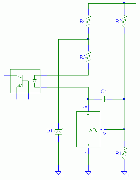
opt coupler
I use TL431 and opt-coupler for my full bridge converter feedback control, but my output voltage is about 200v, if i use voltage divider (200V to 30V for feedback), it does not work.
If vout=200V, Vcontrol drop to 15v rather than 30V
I think it needs a DC isolation, right?
Any suggestion?
I use TL431 and opt-coupler for my full bridge converter feedback control, but my output voltage is about 200v, if i use voltage divider (200V to 30V for feedback), it does not work.
If vout=200V, Vcontrol drop to 15v rather than 30V
I think it needs a DC isolation, right?
Any suggestion?