Continue to Site

Welcome to EDAboard.com

Welcome to our site! EDAboard.com is an international Electronics Discussion Forum focused on EDA software, circuits, schematics, books, theory, papers, asic, pld, 8051, DSP, Network, RF, Analog Design, PCB, Service Manuals... and a whole lot more! To participate you need to register. Registration is free. Click here to register now.

how to drive half bridge mosfets

Status
Not open for further replies.

baggio

Newbie level 3
Joined
Dec 25, 2008
Messages
3
Helped
0
Reputation
0
Reaction score
0
Trophy points
1,281
Activity points
1,303
mosfet half bridge

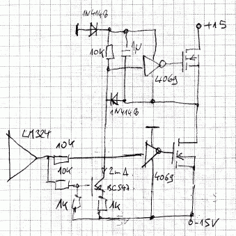
hi everybody...i have to design d class amplifier but i couldnt drive half bridge...can anyone help me...the first picture is output of the comparator(U4A)..i have to aplify this pwm signal in the output of mosfets....but i cant:( please help me guys...could u please make a driver circuit wiht transistor between comparator and mosfets to drive them...?

**broken link removed**

**broken link removed**
 

half bridge circuit

You should specify the intended half bridge circuit and supply voltage. For NMOS bridges, level shifting drivers as IR2110
are always an option. You only need to convert the comparator output to HIN and LIN control voltages.

As another point, LM324 is only usable for KHz switching frequencies. Typical class D applications are rather using
above 100 kHz. For a few kHz only, also MOSFET driving would be much easier.
 

mosfet half bridge circuit

it is my school project and i have to finish it till monday...could somebody design a driver circuit for me?please it is so important...

Added after 52 minutes:

u said '' You only need to convert the comparator output to HIN and LIN control voltages.''

could u explain that?
 

how to drive mosfets

convert the comparator output to HIN and LIN control voltages
This was meant for interfacing an IR2xxx half bridge driver. If U4A is driving the high side switch (HIN), the inverted signal
must drive the low side switch (LIN). You can e.g. use another LM324 respectively a comparator with inverted connection of
both inputs. The most simple interface to IR2xxx would be a series resistor (e.g. 10K) to limit the IR2xxx input voltage
by it's substrate diodes.

But there are several unanswered questions: half bridge supply voltage, transistor polarity, intended switch frequency (if higher
than 600 Hz shown in he waveform)?
 

half bridge switch mosfet

ohh man...you know lots of things..if i knew what you know i could drive mosfets:D could u please draw what u told me...i guess i dont understand...please it take just 10 minutes for you
 

half bridge mosfet driver

A basic circuit of a level-shifting driver following the LM324 output.
88_1230331698.gif
 

half-bridge drive circuits projects

These same questions are on so many websites that I lost count.

Get rid of the lousy old very slow LM324 quad opamp.
 

half bridge

A PWM with 600 Hz switching frequency can use a LM324 without any problems. I understand, that it's intended rather as a
demonstration of the principle than as a real inverter. So far it's O.K. with LM324.

A real design would start by defining a switching frequency and choosing appropriate parts, most likely using a
PWM controller IC instead of an OP ramp generator.
 

Status
Not open for further replies.

Similar threads

Part and Inventory Search

Welcome to EDABoard.com

Sponsor

Back
Top