Continue to Site

Welcome to EDAboard.com

Welcome to our site! EDAboard.com is an international Electronics Discussion Forum focused on EDA software, circuits, schematics, books, theory, papers, asic, pld, 8051, DSP, Network, RF, Analog Design, PCB, Service Manuals... and a whole lot more! To participate you need to register. Registration is free. Click here to register now.

Bias Tee-Design or Circuit

Status
Not open for further replies.

chandregowda

Full Member level 4
Joined
Jul 7, 2008
Messages
212
Helped
14
Reputation
28
Reaction score
4
Trophy points
1,298
Location
Bengaluru/Bangalore, India
Activity points
2,564
bias tee circuit

hi,

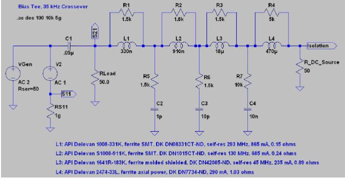
can any body suggest me how to design a bias tee that works for GSM 1800MHz,
(Frequency range 0.1MHz to 1800MHz).

suggest if any book/link/papers

thanks in advance
 

bias tee design

**broken link removed**
 
bias t design

I can provide you with the info (manufacturer, part number) on the inductor suitable for your broadband design. PM
 
wideband bias tee

coilcraft have coils for these type of application that works up to 40GHZ.

(conical inductors in rf section)
 

bias t circuit

hi,

Hey "Vfone", Do you have some more information or any other way on wideband Bias tee design?


sorry that i didn't get complete idea from the second link
 

bias-t design

U may use high-Q inductors for designing wideband Bias tee,
it's large enough for 0.1MHz and its resonance freq in series larger than 1800M is enough.
 

bias-t circuit

>will you make me to understand this circuit?
>there are 2 AC sources, AC1 and AC2.
>why is it?

Since I designed it, I must know how it works! Full details on this circuit, and wideband bias tees in general, is available at: http://web.me.com/gwj/iWeb/Site/S_Param_Test_Set_files/Bias_Tee_Design_V1.pdf

To answer your question, AC2 is added for the purpose of extracting S11. AC1 has an internal 50 ohm source resistance and the amplitude at its output is 1.0 V when the load is matched. AC2 is equal, and opposite, of that, so the voltage at S11 is zero when the match is perfect. More info on this method of extracting S parameters in Spice is available from **broken link removed**

-Gary, WB9JPS
 

Design_of_Bias_Tees_for_a_Pulsed-Bias_Pulsed_RF_Test_System:
**broken link removed**
 

Attachments

  • Design_of_Bias_Tees_for_a_Pulsed-Bias_Pulsed_RF_Test_System.pdf
    697.7 KB · Views: 279
are you going to design it on-chip of off-chip?
 

Hi,

For on-chip bias-tee design, is it possible to reach 40GHz+ with micro-strip lines? If not, is there any other method to do that?


Thank you,
Mario Young
 

I haven't seen any on-chip bias tee that can be up to 40 GHz. You can take a look at: Micro-Bias-Tees Using Micromachined Flip-Chip Inductors
and
Miniature Bias-Tee Networks Integrated in Micro-coaxial Lines
These two papers
 
  • Like
Reactions: mycw

    mycw

    Points: 2
    Helpful Answer Positive Rating
here are the papers
 

Attachments

  • 05616310_biasttee_zoya.pdf
    973 KB · Views: 316
  • 01210983_biastee_ozy2.pdf
    388.1 KB · Views: 283
Just for curiosity, how do we implement broadband (i.e. 40GHz+) bias-tee? Using discrete components? Coplanar waveguide? Because I saw from Picosecond a bias-tee up to 50GHz.
 

Well, as low as possible.
 

Up to 40G, do you use microstrip or waveguide? If use microstrip, maybe you can use inductor up to 40G. Piconics have such inductors from 10M to 40GHz.
 

Status
Not open for further replies.

Part and Inventory Search

Welcome to EDABoard.com

Sponsor

Back
Top