Continue to Site

Welcome to EDAboard.com

Welcome to our site! EDAboard.com is an international Electronics Discussion Forum focused on EDA software, circuits, schematics, books, theory, papers, asic, pld, 8051, DSP, Network, RF, Analog Design, PCB, Service Manuals... and a whole lot more! To participate you need to register. Registration is free. Click here to register now.

CMFB for high linearity and low noise design

Status
Not open for further replies.

jnuhope

Member level 2
Joined
Apr 10, 2007
Messages
51
Helped
4
Reputation
8
Reaction score
0
Trophy points
1,286
Activity points
1,566
high linearity follower

Hi all,

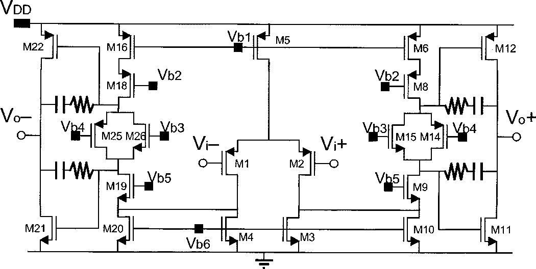
I am designing an opamp for audio application. The opamp needs to achieve high linearity and low noise. For high linearity, resistor type of CMFB seems to be a good candidate, but big resistors introduce noise. My question is what kind of CMFB is good to achieve both linearity and low noise? What's the common CMFB architecture used in audio application?

Thanks everyone in advance!

ps: the CMFB has to be continuous becuz of the application.
 

cmfb for low output swing

ok. I think that is the best solution for linearity reasons. But it needs a two stages opamp with a low output resistance. In that way you can use lower resistances to the common mode sense.
 

    jnuhope

    Points: 2
    Helpful Answer Positive Rating
cmfb noise

danielpasti said:
ok. I think that is the best solution for linearity reasons. But it needs a two stages opamp with a low output resistance. In that way you can use lower resistances to the common mode sense.

Can you explain in more detail? Two stage opamp means the main opamp right? What do you mean to use lower resistances to the cmfb sense?

Thanks!
 

cmfb sense

ok ...first sorry for my english, Im brazilian. If you already use a two stage opamp (differential pair + output stage), maybe you will have a tradeoff between noise and this resistance-based solution. In my designs I use a 10k resistor and I adjust the CM pole by the shunt connected capacitor and the capacitance Cgs of the MOS conected on then. Depending on the signal amplitude you are using it will not decrease your SNR. By the way, what kind of noise are you worried, white noise or flicker noise ?
Regards

Added after 5 minutes:

Maybe if you post your circuit here I can help you better.


The opamp is the same architecture as Annovazzi et.'s paper of jsscc july 02. and is used inside for a RC active filter.

Two questions:

1. How many CMFB is needed for this kind of structure? Can we do two cmfb instead of one for his opamp?

2. If I use resistor type of cmfb as sensing ckt, will the resistors add up to the total noise?

Thanks for any inputs.
 

1, it only need one CMFB ckt here;
2, resistors add little noise because of opamp gain.
 

    jnuhope

    Points: 2
    Helpful Answer Positive Rating
ok ...that is a folded cascode with translinear class AB output stage. For this topology I do believe that the resistor sense would be a good choice. You can choose a lower value of resistance as long you decrease the output resistance of you output stage. In that way you will not load the output stage with the sense resistors. Dont forget that the "common mode" closes a different loop of the "differential mode", so it must to be compensated too.
Regards
 

    jnuhope

    Points: 2
    Helpful Answer Positive Rating
I won't worry about noise at all since your output is differential. All noise contribution from CMFB loop is common mode -- it won't be visible at the differential output.

Resistor sensing will cause lower differential mode open loop gain at the output - if the resistor too low, more distortion you may see. A unity gain buffer at each output (eg source follower) shall serve you well in this regard. Tap the common mode signal from the resistor divider at the output of those two buffers.

If you worry about the buffer input cap non-linearity loaded to your output, just put dummy mos cap cross coupled to cancel out. Or add series resistor to the gate.
 

    jnuhope

    Points: 2
    Helpful Answer Positive Rating
xshou said:
I won't worry about noise at all since your output is differential. All noise contribution from CMFB loop is common mode -- it won't be visible at the differential output.

-- Well said! Got you!

Resistor sensing will cause lower differential mode open loop gain at the output - if the resistor too low, more distortion you may see. A unity gain buffer at each output (eg source follower) shall serve you well in this regard. Tap the common mode signal from the resistor divider at the output of those two buffers.

If you worry about the buffer input cap non-linearity loaded to your output, just put dummy mos cap cross coupled to cancel out. Or add series resistor to the gate.

-- Can you explain more why the series resistor to the gate will cancel or help the non-linearity caused by the input cap?

Thanks!
 

"I won't worry about noise at all since your output is differential. All noise contribution from CMFB loop is common mode -- it won't be visible at the differential output. "

Excuse me Xshou

Always there is a confusion between NOISE and INTERFERENCE source. Noise is a king of random frequency (not deterministic) coming from the components in the circuit. Interference is a external disturb which "strikes" the circuit in common mode and are attenuated by the CMRR capability of it. In fact, the noise has a attenuation of 10dB of power in differential circuits comparing with single ended circuits.

Added after 4 minutes:

"Resistor sensing will cause lower differential mode open loop gain at the output - if the resistor too low, more distortion you may see. A unity gain buffer at each output (eg source follower) shall serve you well in this regard. Tap the common mode signal from the resistor divider at the output of those two buffers."

The use of a source follower in your circuit will decrease the common mode swing of your circuit because it has a Vgs of drop before the resistors. I
 

danielpasti said:
"I won't worry about noise at all since your output is differential. All noise contribution from CMFB loop is common mode -- it won't be visible at the differential output. "

Excuse me Xshou

Always there is a confusion between NOISE and INTERFERENCE source. Noise is a king of random frequency (not deterministic) coming from the components in the circuit. Interference is a external disturb which "strikes" the circuit in common mode and are attenuated by the CMRR capability of it. In fact, the noise has a attenuation of 10dB of power in differential circuits comparing with single ended circuits.

Added after 4 minutes:

Due to the nature of fully differential opamp, noise from CMFB shall not contribute much to the differential output signal. I don't understand your claim "noise has a attenuation of 10dB of power in differential circuits". Provide more details please. And I don't see why it is relevant here.

danielpasti said:
"Resistor sensing will cause lower differential mode open loop gain at the output - if the resistor too low, more distortion you may see. A unity gain buffer at each output (eg source follower) shall serve you well in this regard. Tap the common mode signal from the resistor divider at the output of those two buffers."

The use of a source follower in your circuit will decrease the common mode swing of your circuit because it has a Vgs of drop before the resistors. I

Not at all. One can implement the same Vgs drop on the reference side for the cmfb error amplifier. If rail-to-rail output swing is needed, try to make a current steering complementary scheme with pfet and nfet source followers.

Added after 6 minutes:

jnuhope said:
xshou said:
I won't worry about noise at all since your output is differential. All noise contribution from CMFB loop is common mode -- it won't be visible at the differential output.

-- Well said! Got you!

Resistor sensing will cause lower differential mode open loop gain at the output - if the resistor too low, more distortion you may see. A unity gain buffer at each output (eg source follower) shall serve you well in this regard. Tap the common mode signal from the resistor divider at the output of those two buffers.

If you worry about the buffer input cap non-linearity loaded to your output, just put dummy mos cap cross coupled to cancel out. Or add series resistor to the gate.

-- Can you explain more why the series resistor to the gate will cancel or help the non-linearity caused by the input cap?

Thanks!

By putting series resistors, you lower the capacitive loading on the your differential output at high frequency due to CM sensing. Thus lower the nonlinear effect from the gate cap -- note the output impedance of the current source for source follower can have similar effect.
 

xshou

Im sure you can read with more details in Gray n Mayer book about the NOISE contribution on diff output stages. You will increase the SNR because the doubled output stage. This means 3dB of power or 6dB of voltage. I wrote 10dB but I was wrong.


About the source follower as sensing the output vref, I can say to you that you need the same output swing for diff mode and for common mode to keep CMRR and reference over all the signal level. You can read it in the same book I mentioned above.

Sorry for my english dude, I am Brazilian

Regards
 

danielpasti said:
xshou

Im sure you can read with more details in Gray n Mayer book about the NOISE contribution on diff output stages. You will increase the SNR because the doubled output stage. This means 3dB of power or 6dB of voltage. I wrote 10dB but I was wrong.

I don't see any reason you need introduce SNR to our discussion. I don't need gray & meyer to know differential output has double the signal swing at output compared to single ended. So far I haven't seen anyone tried to use fully differential opamp output single-ended (though some people apply single ended signal at input). Thus you comparison is completely unnecessary.

But why is it relevant here?

As I said before, CMFB doesn't introduce additional noise at differential output. I believe OP got my point quickly.

As in the schematic, CMFB controlling Vb2 or Vb5 shall not introduce extra noise at differential output.

danielpasti said:
xshou

About the source follower as sensing the output vref, I can say to you that you need the same output swing for diff mode and for common mode to keep CMRR and reference over all the signal level. You can read it in the same book I mentioned above.

Sorry for my english dude, I am Brazilian

Regards

My Brazilian friend, it's absolutely unnecessary to have the same output common mode swing as differential mode swing. Why do you want your common mode output to be rail? Do you still have some differential mode gain when output common mode is rail (think about your 'keep CMRR and reference over all signal level')?

Please don't point me to gray&meyer again. I have to say your description of fully diff opamp is misleading and confusing.
 

xshou,

I believe daniel just wanted to express that he may not cover the whole details in his post and suggested that one can find more details in the book. That's why he keeps mention his English may not be perfect ( whose English is perfect here? we are not marketings, right? :)

On a side note, do you see the opamp architecture
above can reach 100+ dB while driving a 8 ohm load? Thanks!
 

My anywhere friend

Im sorry for my enlgish. Maybe I were not well "interpretade" when I sad you to find out more on gray n meyer about NOISE.
And I see you wont do that mainly because your proud. All I wrote above Im sure you can find in any book as high as you.

About opamp dont forget you can set (by resistors) its gain for 1. How is the noise between resistors when the gain is unity ?
 

Status
Not open for further replies.

Part and Inventory Search

Welcome to EDABoard.com

Sponsor

Back
Top