Continue to Site

Welcome to EDAboard.com

Welcome to our site! EDAboard.com is an international Electronics Discussion Forum focused on EDA software, circuits, schematics, books, theory, papers, asic, pld, 8051, DSP, Network, RF, Analog Design, PCB, Service Manuals... and a whole lot more! To participate you need to register. Registration is free. Click here to register now.

"Lead" or "Lag" in phase detector?

Status
Not open for further replies.

steadyj

Newbie level 6
Joined
Aug 17, 2008
Messages
13
Helped
1
Reputation
2
Reaction score
1
Trophy points
1,283
Activity points
1,390
Hi all, I am confused about the judge of "lead" or "lag" in phase detector.

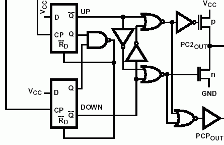
Figure 1 is a phase detector. Figure 2 is the waveform when A leads B. But the fact "A leads B" seems to depend on the initial time. As shown in Figure 3, if the initial time is the red vertical line, it becomes "A lags B". And the output pulses will be on Qb instead of on Qa.

So what is wrong with my logic? I believe phase detector should work in a reliable way instead of depending on the arbitrary initial time. What is the real way phase detector works?
 

what is initial time in a real circuit? Only a fiction. Actually, the power supply is turned on at an arbitrary moment and the FFs initial states are unknown anyway. So a edge counting phase detector will have an in initially uncertainty of one cycle. But it's no problem in any real application (typically a PLL). I guess, you'll findout, why.
 

I really don't know why. For instance, A is the reference input and B is the VCO output. After power on, B's frequency is lower than A. So we wish the phase detector can output voltage on the "UP" port. Unfortunately the uncertainty after power on maybe make the contrary action, which seems to un-lock for ever.
-- Please correct me. Thank you.
 

steadyj said:
Figure 1 is a phase detector. Figure 2 is the waveform when A leads B. But the fact "A leads B" seems to depend on the initial time. As shown in Figure 3, if the initial time is the red vertical line, it becomes "A lags B". And the output pulses will be on Qb instead of on Qa.

I am afraid, your understanding of the term "lead" is not correct.
"Lead" does not mean that the pulse train is "more to the right" - just the opposite is true: Take your red line and verify that the train A is already in a high state and train B is not. Therefore, A leads B.
 

Unfortunately the uncertainty after power on maybe make the contrary action, which seems to un-lock for ever.
Comparing your circuit with a 4046 digital phase detector, that is known not to have similar issues, it should work.

49_1219482790.gif
 

Status
Not open for further replies.

Part and Inventory Search

Welcome to EDABoard.com

Sponsor

Back
Top