Continue to Site

Welcome to EDAboard.com

Welcome to our site! EDAboard.com is an international Electronics Discussion Forum focused on EDA software, circuits, schematics, books, theory, papers, asic, pld, 8051, DSP, Network, RF, Analog Design, PCB, Service Manuals... and a whole lot more! To participate you need to register. Registration is free. Click here to register now.

calculation center-tapped transformer

Status
Not open for further replies.

jancambodia

Newbie level 6
Joined
Feb 27, 2008
Messages
13
Helped
0
Reputation
0
Reaction score
0
Trophy points
1,281
Activity points
1,384
center tapped transformer

Hi

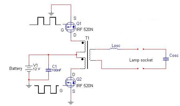
I have the following circuit of a CFL ballast.


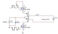
For the design I want to calculate the transformer, but I'm not sure how to do it because of the center tapped configuration. There is a 12V source connected to the center of the primary.

(1)

When I measure the voltage at the drain (mosfet that is turned off), I measure a voltage of 24 Volts. I would like to know how this is possible.

(2)

I want to know the input voltage of the transformer, is this a 24+24= 48 Vpp voltage? Is it possible to calculate this transformer in the same way as a transformer with 1 primary coil?

Thanks
 

transformer winding calculation

1. I could hardly imagine how the circuit should operate without an off-state voltage at the drain above Vbat, as the mean voltage difference (DC voltage) at an transformer winding or an inductor must be zero. This would also be the case with a single ended inverter and single primary coil. Assuming ideal coupling, the momentary voltages at both primary coils have equal magnitude, so it's also obvious that when a switch is closed (Vds1 = 0), for the opposite switch Vds2=2•Vbat must be kept.

2. Yes, the voltage transformation relations doesn't depend on the number of windings or on possible taps. You can calculate it for a partial winding as well as a for a total winding.
 

transformer winding calculations

I measured the voltage across the two drains and it was 48 Vpp. The voltage on the secondary was 90 Vpp (no load attached). I can't figure out how to get this voltage. I have a turns ratio of 25+25:75, so the voltage transformation must be 3 times.

For example, if I take 1 primary coil. There is a voltage of 12V across it in the on-state. The turns ratio is 25:75, so this voltage has to be 3 times higher. 3 x 12 = 36 Vpp, which is not the same as half the secondary voltage (0.5 x 90 Vpp = 45 Vpp)

Are my calculations correct, plz let me know
 

centre tapped transformer calculation

I assume, you measure the voltage with an oscilloscope (I know no other instrument that is measuring regularily Vpp). Why don't you just try to understand what you see instead of comparing assumed values with measured values? If you don't have an oscilloscope, it is actually difficult to understand the circuit behaviour exactly.

Basically, the calculation would be correct for an ideal tranformer, as I already mentioned. Assuming your winding ratio specification is correct, the measurement shows, that the transformer isn't ideal, most likely the difference is due to stray inductance. What causes the difference can better be seen with an oscilloscope than predicted theoretically, although it can be calculated and simulated if necessary.
 

characteristics of centre tapped transformer

When one Mosfet conducts, its winding of the transformer has 12V across it and the other winding has a voltage that goes up to +24V so that it also has 12V across it. One 12V winding couples 12V to the other winding because it is a transformer.
From winding to winding there is 24V p-p.

If you are feeding the circuit from a fully charged lead-acid battery that has a voltage of 13.8V then the 3 times turns ratio will make an output voltage of 82.8V p-p.
The inductance of the transformer might add some voltage spikes.
 

turns ratio calculation centre tapped

I measured the voltages with a oscilloscope. I don't have a lot of exeperience in the field of magnetics, so to understand what I see is sometimes difficult. By stray-inductance you mean the leakage inductance? Can you tell me how to see with the oscilloscope where this difference is coming from, so I can try to minimize this effect. Thanks
 

transformer calculator ver 3.0

It's no said, that you necessarily must reduce stray, leakage or parasitary inductance (The terms are equivalent to my opinion). At the output, you have a series inductor anyway, some more stray inductance between primary and secondary would just add to Losc. The transformer could be build even as resonance transformer completely eleminating Losc respectively embedding it in the transformer.This is usually done for CFL switchers with a half-bridge instead of the shown push-pull configuration.

With the shown push-pull configuration, stray inductance between respectively non-ideal coupling of the primary windings cause overvoltage at the transistors in off phase. It may stress the transistors voltage capacity and increase switching losses. So with this configuration, it is probably desirable to have a tight coupling of the primaries. This could be achieved e. g. by bifilar windings.
 

Status
Not open for further replies.

Part and Inventory Search

Welcome to EDABoard.com

Sponsor

Back
Top