Continue to Site

Welcome to EDAboard.com

Welcome to our site! EDAboard.com is an international Electronics Discussion Forum focused on EDA software, circuits, schematics, books, theory, papers, asic, pld, 8051, DSP, Network, RF, Analog Design, PCB, Service Manuals... and a whole lot more! To participate you need to register. Registration is free. Click here to register now.

74hc595 noise problem ?

Status
Not open for further replies.
74hc595 problems

we have these results
when we use .1uf cap on every 74hc595 power rail the problem is got worst
and so we take them and put 74hc245 on the way of DS, SCK,LCK of the twentieth
74hc595 to the end of the display(twenty fifth 74hc245) the problem is got better
and with this configuration plus a 27pf cap on the last 74hc595 LCK pin the problem is
solved!!! if anybody know why the problem is becoming worst when we use .1uf cap on every 74hc595's power rail plz describe it for me .
thanks for every one's help
 

74hc595 led signed schematic

Hi,

I'm glad that you solved your problem with the shift registers.
The problem with the capacitor can occur due to a parasitic oscillation. You can have an equivalent inductance of the power supply line or maybe you already have an inductor on it. Now, picture that you have the right LC combination required for a sustained oscillation. You can eliminate it by connecting a larger capacitor 1-10uF in parallel with the 0.1uF or you can insert a series resistor (1-2ohms) between the supply rail and the hc595 supply pin with the capacitor connected to it. This way you lower the quality factor (Q) of your decoupling group and eliminate the oscillations.

Best regards!
 

pic16f 7x40 led

Hello to all

i need help regarding the led moving message display 8x80

i am trying to build the led moving message so for start i made 8x40 it using mikroc compiler

the hardware is pic16f877a , 74hc595

for rows i am connection through 100 ohms from portd to 8 rows and for cols driving through 74hc595

its was working great but since yesterday its not working as a good

i want to use uln2003 or uln2803 for cols and for rows want to use transistors but i don't no much about eelectronics i am a computer programmer in vb

pls can any bedy help me regarding this to make good hardware i be so thank ful\

pls pls
 

รูป ic 74595

Schematic for Moving Message Display 7x40 pixel

7 x IRF9540 for rows
8 x 74hc595 + ULN2003 for cols
1 x PIC16F627A for control
1 x MAX232 for comunication

2 Input for setting (etc.)
maximum refresh rate for this schematic 500Hz
 

ic 74595

Put on last ic 74hc595(U25) pin 12(latchclk) to gnd 27pF and 1k resistor

Hey PICS, can you tell me how to put 1k resistor & 27pf on pin 12, i mean pin 12 then capacitor then resitor to ground or resistor & capacitor in parallel.
One thing more as pin 12 of all 74595's are connected together will it make a difference whether i connect it to 1st one or last one?

Thanks

Regards,
Garg
 

difference between uln 2003 uln2803

See R41 & C10 from my schematic

Conect R41 & C10 to last pin12 of 74HC595,first pin12 conect to MCU
 

row 74595

Hello Omid Juve

i have build 1 led moving emssage 8x80 its working good but the brightness is not good i have connected rows directly from portd and for cols scanning from 74hc595 i not attached any uln nor any resistors its connecting direcly pls can u seuggest me what resistors i have to use

acutaly i want to use same like u 74hc595 and uln2003 and for rows want to use same 74hc595 so that i can drive 16 rows can u tell me how ur driving 16 rows coz pic16f877a and pic18f452 is only 8 bit are u sing 2 ports or using any ic

pls can u suggest me how can i use uln2003 i am learning embed so started this project

i be so thank ful to u

thanks alot
 

tpic6b595

Dear PiCS,

Your 7x40 design is very nice but uses far too many ICs. Have you considered;

(1) Using five 'HC595 / '2003 pairs to drive 40 columns instead of eight pairs?
(2) Using five serial-to-parallel sinking driver ICs instead of 'HC595 / '2003 pairs?
(3) Using five serial-to-parallel constant current sinking driver ICs instead (no current limiting resistors required)?
(4) Modulating the 'HC595 or other drivers mentioned above with PIC PWM signal for full fade-to-black brightness control?

Here's a variation of the design for your consideration. You could still load 40 bits of column data into cascaded driver IC shift registers if you like but you could also take advantage of the PWM signal to multiplex those row driver lines and use them to load the driver IC shift registers in parallel during a small blanking interval at the beginning of each interrupt cycle when the PWM line is high and the displays are off. This allows you to load the shift registers simply by throwing 8 bytes onto the bus with a clock pulse after each byte. Of course you still need to format the 8 special bytes later in the ISR with all of the b7 shift register bits in one byte, b6 shift register bytes in another byte, and so on for the next interrupt cycle, but this takes very little code and time.

Display brightness is inversely proportional to PWM duty cycle and the PWM period must equal the row scan interval. A 100% duty cycle corresponds to 0% brightness (a 'black' display). Use something like a 2% min. duty cycle (98% max. brightness) to allow enough time for a small blanking interval to load the driver IC shift registers at the beginning of each interrupt cycle.

Kind regards,

Mike K8LH
 

how to fade led with ic 74hc595

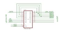
I hade the same problem. Multiply cascading of more than 4 pcs of 595s generating delay problem between Serial Data signal and Clock. My solution can see on the picture. After each fourth 595 put one hc573 for improving quality all signals and correcting data delay signal.

good luc


Added after 5 hours 54 minutes:

I ammsorry, I made a mistake. This is correct wiring of 573. Output Serial Data delay signal is depend of type or brand 595's.


hc595 problems

The problem seems like a impedance mismatch. İf you drive a long line and with somehow high frequency . The strip line of PCB behave like a high impedance line.
The solution is to put a stub in between clock and gnd line a shunt resitance. The value of the resistance should be found by using a pot. COnnect the potentiometer at the end of you CLOCK line between GND and adjust till you obtain the wanted results.
hope it helps you

cheers
 

how to connect 74hc595 schematic

Hi guys can you recommend me what is the best shift register from those two when designing a long LED matrix?

74HC164 or 74HC595 ?

I made one with 74HC164 but the display is not smooth.
 

74595 pwm

i think the 74hc595 is better because of the latch option and the output enabled pin you can control the brightness by using a PWM signal
 

HI,
I have some strange problem, I have a 4 identical PCB’s with 74hc595 and UNL 2003 which driving only seven segment led
If I connect 3 of them it is fine but when I connect the last one 4PCB then I getting random segments on, I decuple the power on each 74hc595, at the latch (store) res/cap but still getting unaccepted result, the software running fine on Proteus but not in real life on pcb.
Any suggestion will be appreciated
 

Attachments

  • 1.jpg
    1.jpg
    81.3 KB · Views: 129

Status
Not open for further replies.

Similar threads

Part and Inventory Search

Welcome to EDABoard.com

Sponsor

Back
Top