Continue to Site

Welcome to EDAboard.com

Welcome to our site! EDAboard.com is an international Electronics Discussion Forum focused on EDA software, circuits, schematics, books, theory, papers, asic, pld, 8051, DSP, Network, RF, Analog Design, PCB, Service Manuals... and a whole lot more! To participate you need to register. Registration is free. Click here to register now.

why positive S11 of patch antenna ?

Status
Not open for further replies.

TWang

Junior Member level 1
Joined
Sep 12, 2007
Messages
15
Helped
0
Reputation
0
Reaction score
0
Trophy points
1,281
Activity points
1,415
Hello everyone,

It's a problem that confuses me very much.
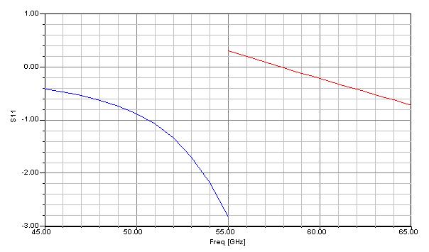
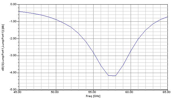
As I tried to use HFSS to simuate a 60GHz patch antenna, I got positive s11 all the time. Where were I wrong? Could anyone kindly tell me the possible reasons of this strange results. Thank you.

the patch is 1.4mm x 1.4mm with pcb(Er=3, 0.13mm thickness)
i use lumped port inside the pcb.
i did let the radiation boundary away from the structure by quater wavelength.
 

Can you upload your file here, so we can look at it & can tell you what is going wrong.
 

Here is the sim format i used. The solution frequency is 65GHz.
I seperate the freq sweep to two parts, one is from 45~55GHz, the other one is from 55~65GHz, but the results show that there is a discontinuity at the bounary of 55GHz as the attached plot. It's so weird.
[/img]
 

Are you sure you are plotting log mangnitude of S11?
 

Yes I did. The conclusion i have right now is sometimes the s11 is normal but sometimes it is not. Here is another result. i sweep the freq in step from 45G to 65G. This time it's normal again.


Another problem confusing me is i have antenna efficiency larger than one, did anyone have such weird result before ?
 

Hi TWang
I think the positive S11 results show that our simulation hasn't convergence and we should change our simulation parameters such mesh, simulation frequency, feed structure,...
i hope it'll be helpful
 

I was just reading the on line documentation on HFSS lumped port and notice that they say the s matrix can sometimes have values greater than 1. You might look into that and see if that is the root of your concern. Sometimes reading that stuff (over and over) helps.

I generally have better results with wave ports. Just an observation. I wonder if you would see the same issue with a wave port.
 

Try changing Radiation Boundry.
Use different materials such as Air,Vacuum & see the effect.
 

Thank you guys for giving me these suggestions. According to my recent experience in simulating this antenna. I found that the air box should be bigger enough, but of course it will cost lots of time. Maybe it's better to use 2D simulator instead of 3D.
 

HFSS is a very useful software package. There are situations, however, where others have advantages and patch antenna evaluations is one. The Ansoft folks recommend their Designer package (a so called 2.5 D code) for patch antenna work and describe it as faster and less demanding on computer resources. If your feeds are not too unusual this might be a good alternate.
 

Status
Not open for further replies.

Part and Inventory Search

Welcome to EDABoard.com

Sponsor

Back
Top