Continue to Site

Welcome to EDAboard.com

Welcome to our site! EDAboard.com is an international Electronics Discussion Forum focused on EDA software, circuits, schematics, books, theory, papers, asic, pld, 8051, DSP, Network, RF, Analog Design, PCB, Service Manuals... and a whole lot more! To participate you need to register. Registration is free. Click here to register now.

Sigma-Delta Modulator in Fractional-N frequency synthesizer

Status
Not open for further replies.

hmsheng

Full Member level 4
Joined
Dec 17, 2003
Messages
219
Helped
26
Reputation
52
Reaction score
10
Trophy points
1,298
Location
China
Activity points
1,556
dither dsm

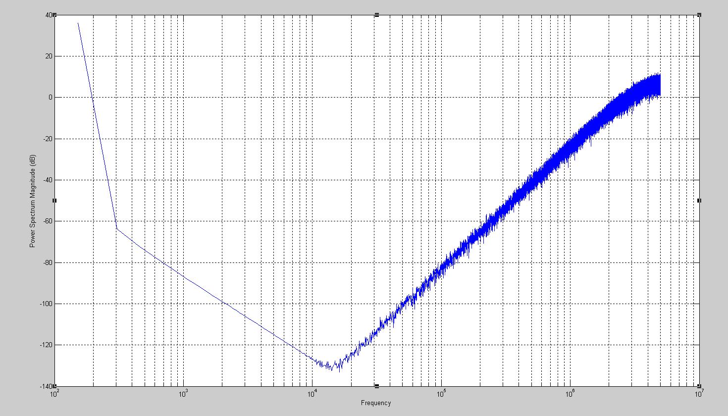
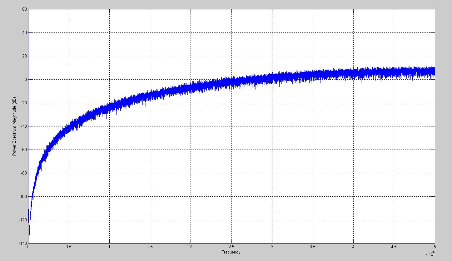
It's known that a spur free fractional-N frequency synthesizer is mostly realized with a sigma-delta modulator and a multi-module divider. The control bits of the multi-module divider is dithered by the sigma-delta modulator (SDM). But the output of the SDM is a cyclic data series. If the accumulator has m bits, then the output of SDM will repeat after 2^(m+1) clock cycle for a 3rd order SDM. A cyclic control bits for the multi-module divider will cause spur. So, why said it's spur free?
 

frequency synthesizer 1:1 1:256

when dither is added, the dsm output will not be cyclic . The location where dither is added is very important.
 
swicap,

Don't you think SDM is a way of dither?
 

It is.
But for different DC input, DSM has different performance. Many theories try to explain this.
That is why dither is so important in Delta sigma pll
and time domain modeling is necessary.

for a 1st order DSM, the best location to add dither is the node before the comparator(1 bit ADC), but sometimes we use accumulator to implement a DSM. It is called 'compact 1st order DSM'. for this structure, there is no such a node. We may add dither to the input or output. It is also effective, but
there is performance loss, because the added dither,in fact also noise, can't be shaped which means more in_bandwidth phase noise of pll.
 

Re: Sigma-Delta Modulator in Fractional-N frequency synthesi

If the output of the SDM for a fractional synthesizer only have two states a you have a critical numer like 23+1/256 there is NO other way than 255 times 23 and ONE 24. So the spur pops up in the frequency range where the PLL analog filter does not filter!

Build a multi-number SDM FIRST!

The try SDMs which approach the gaussian number distribution.
 

Very good topic, and I learn a lot from your discussion.

dear rfsystem
I wonder how you get the conclusion the spur pops up in the frequency range where the PLL analog filter does not filter!
Is it fref*1/256 < bandwidth of LPF ?

dear swicap
If with a traditional MASH1-1-1 structure, how will dither affect the performance?
I mean I know that the dither will eliminate the idle tones and rise the noise floor. But how worse will the noise performance become with different dithers?


And as I know there is two way to do it. One is to dither the LSBs of the input K. The other is to set the first accumulator LSB to be 1 each time when reset.
I want to know which way is better, or is there any other good way to do it ?
And if I chose the first method, how can I decide how many LSBs to dither?

Those questions really confused me for quite a long time.
Please help me out~~~~
 

Re: Sigma-Delta Modulator in Fractional-N frequency synthesi

Hi, leo:

There is a trade off.
So a system level simulation is needed. u can evalue ur system and determine
these parameters on basis of ur sim results. I use matlab/simulink programs.
beside, u have to take pll bw in to ur calculation.

Both method are ok, the first is used more often.
if u don't know the optimal dither amplitude, u can set some registers to control
it.
 

Re: Sigma-Delta Modulator in Fractional-N frequency synthesi

Thanks for your reply
Because I don't know how to realize a full adder and register in simulink. So I set up a MASH1-1-1 model with 1/z module based on the theory Z domain transfer map.
And I add Band limited white noise, or repeating sequence model as dither. But as I changed the noise power or the sequence content , I didn't find any change in the PSD map.
Is it because the 1/z model is idea ? As I thought it should affect the noise floor in low frequency...
I use the psd(name,number,frequency) command to plot the map, and uses log in the X axis .

regards
Leo

Added after 4 hours 12 minutes:


This is my simulation result.
I think there is something wrong with the low frequency curve, but I don't know how to improve ...
 

hello leo
may i ask you a favor !?
may u upload the block diagram or the matlab code for the mash 111 SDM.
i have a sever problem in simulating this topology.
thanks leo
regards,
hazem
 

Re: Sigma-Delta Modulator in Fractional-N frequency synthesi

Leo_fish said:
......
This is my simulation result.
I think there is something wrong with the low frequency curve, but I don't know how to improve ...

Hi, Leo,

1. You must remove the DC value from the data for fft.
2. You can use a window when do fft, this will solved your curve problem at low frequency.
3. Another way, you can do fft with more data points.

Regards,
HM
 

Hi Leo_fish,

I can you explain more on the second way of dithering? when to reset the first accumulator?
I only knows the first method, and simulate it in simulink, it raises noise floor largely, for classic mash 1-1-1.
 

Status
Not open for further replies.

Part and Inventory Search

Welcome to EDABoard.com

Sponsor

Back
Top