Continue to Site

Welcome to EDAboard.com

Welcome to our site! EDAboard.com is an international Electronics Discussion Forum focused on EDA software, circuits, schematics, books, theory, papers, asic, pld, 8051, DSP, Network, RF, Analog Design, PCB, Service Manuals... and a whole lot more! To participate you need to register. Registration is free. Click here to register now.

Phase shifter design with lumped elements

Status
Not open for further replies.

Shoma Chandorkar

Junior Member level 2
Joined
Jun 27, 2007
Messages
22
Helped
1
Reputation
2
Reaction score
0
Trophy points
1,281
Activity points
1,403
phase shifter design

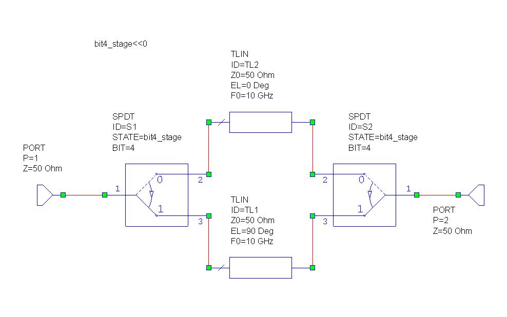
I wanna design 6 bit phase shifter with lumped elements (L & C) using Microwave Office . It can be designed using hign pass and low pass circuit and a pair of SPDT switch. But how this switching will take place?
 

Hello,


There is very good example available in AWR examples folder (Ideal_Phase_Shifter.emp)...Go thru the Design Notes explains how to use the SPDT model...Instead of TLIN models use the Lumped element network...

**broken link removed**

Also go thru Chapter 12 of Lumped Elements for RF and Microwave Circuits book
by Inder & Bahl
Phase shifter schematic - This is an ideal 6 bit phase shifter. The subcircuits in the chain have an ideal switch and ideal transmission lines to generate the phase shift. Each subcircuit has a different phase shift that, when properly combined, give all 64 possible phase states. Each subcircuit has its bit parameter exposed so it can be passed in from the top level schematic. In the schematic there are various ways that the current state is chosen and these will be explained in more detail later. In each subcircuit, the SPDT can decode a state number into individual bits and choose the proper bit to control the switch. For example, in this 6 bit shifter, there are 64 possible states. If you decode this base 10 number to a base 2 number you have 6 bit locations (E.g, 0 in base 10 is 000000 is base 2, 1 In base 10 is 000001 in base 2, and 63 in base 10 is 111111 in base 2). On the SPDT model, you specify a base 10 state number and then which bit in this number. Each shift section is getting the same state number but the bit setting on each switch is different for each subcircuit.


---manju---
 

Status
Not open for further replies.

Part and Inventory Search

Welcome to EDABoard.com

Sponsor

Back
Top