Continue to Site

Welcome to EDAboard.com

Welcome to our site! EDAboard.com is an international Electronics Discussion Forum focused on EDA software, circuits, schematics, books, theory, papers, asic, pld, 8051, DSP, Network, RF, Analog Design, PCB, Service Manuals... and a whole lot more! To participate you need to register. Registration is free. Click here to register now.

[Moved]: Need to add signals, with different frequencies

Status
Not open for further replies.

pkrishnam

Newbie level 3
Joined
May 13, 2010
Messages
3
Helped
0
Reputation
0
Reaction score
0
Trophy points
1,281
Location
Bangalore
Activity points
1,307
Hi,

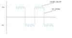
I want to add two signals which is similar to the waveform shown below.

One is NRS signal operating at 330Kbps and for this i want to add a small square wave form which can operates at 1.6MHz and 30mv p/p.

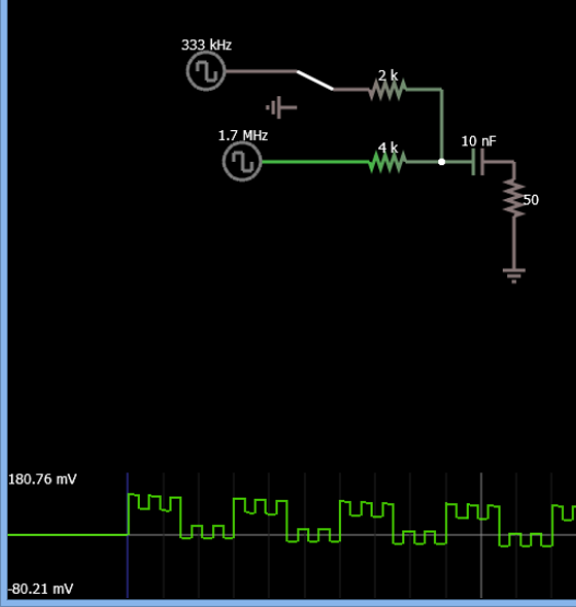
Any input on how this can be achieved will be a great help.

Regards,
Kris
 

Attachments

  • Waveform.jpg
    Waveform.jpg
    327.8 KB · Views: 68

Which tool/simulator do you use?
 

Hi,

I want to add an square wave on top of NRZ or BMC signal which is running at 1.6MHz frequency and 30mV p/p, as shown in the attached waveform.

I want to realize this on a analog device, for input BMC signal i want to add 1.6MHz square wave.

I am not using any tool/simulator, please let me know if any open source tool that can help me realizing this.

Regards,
Kris
 

With a 4:1 ratio on amplitude, your drawing is not to scale. (120:30 mVpp)

With a /5 counter divider you can make the frequency ratio precise.

With 5V logic CMOS, you can easily mix the amplitudes down to your desired level with AC coupling as shown (HPF response )

Here is a quick simulation

8830651700_1454375685.png
 

Hi Sunny,

Thanks for your response.

How the amplitude is maintained 1.2V p/p & i can't add a 2K to the 333KHz signal, will have other effect which can cause the specification to fail.

Is there any method that you suggest without adding this resistance to a input signal?

Regards,
Kris
 

You can add any number of signals in any ratio using an op-amp. If all the input resistors are equal, then the signals are just added but if the resistors are not equal, the signals are scaled and added. But beware of the phase shifts after the amplifier or the capacitor (as seen above). Phase shift is frequency dependent.
 

Resistive addition is the only practical way to go about this, but it may need some buffering either at the input or output, depending on the impedances involved.
 

Status
Not open for further replies.

Part and Inventory Search

Welcome to EDABoard.com

Sponsor

Back
Top