Continue to Site

Welcome to EDAboard.com

Welcome to our site! EDAboard.com is an international Electronics Discussion Forum focused on EDA software, circuits, schematics, books, theory, papers, asic, pld, 8051, DSP, Network, RF, Analog Design, PCB, Service Manuals... and a whole lot more! To participate you need to register. Registration is free. Click here to register now.

How does LC phase shift oscillator work?

Status
Not open for further replies.

Neyolight

Full Member level 5
Joined
Aug 29, 2011
Messages
306
Helped
3
Reputation
6
Reaction score
3
Trophy points
1,298
Location
World
Activity points
3,624
Heya Everyone :smile:

Im slightly confused as to how LC phase shift oscillator work ?

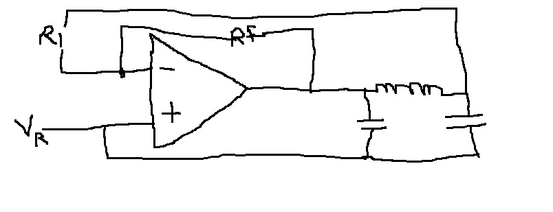
Its a circuit consisting of 1 op-amp ( used as oscillator), 1 LC loop, few resistors. The op-amp has a reference voltage applied to the non-inverting end (+ve).

The inverting end has a feedback resistor and the Vout from the LC loop connected. It looks something like this, except replace the 3RC with 1 LC - **broken link removed**

Ok so whatever Ive read on the internet- 1LC circuit has 2 poles ( not sure what that means :roll:) ,thus it contributes up to 180 degree phase shift per pole pair. RC circuit has a 60 degree phase shift and hence we require 3 of them !

Now, oscillation occur at the frequency were the total phase shift through 1 LC or 3 RC is 180 degree ( WHY????) :roll:

Could someone please explain to me how this works? As im totally LOST !

Thanks :smile:
 

Oscillations begin at switch on, a little bit of noise in the circuit goes around it being amplified all the time, at certain frequencies the net result is positive feedback, i.e. the signal is getting bigger and at other frequencies the feedback is negative and the noise is diminished. Eventually the circuit settles down and oscillates at a certain frequency and depending on the amount of gain and the type of feedback, the output waveform can be anything from a square wave to a pure sine wave.
So the thing is, you need 360 phase shift altogether ( at your selected frequency) and a gain of greater then unity. Most simple amplifiers (single valve or transistor) have a 180 degrees phase shift from input to output so your phase shift network has to put in an additional 180 degrees.
Frank
 
Hi Chuckey, I think your explanations - which are general - are correct, however I doubt if they will help to answer the problem of neyolight.
Question: How can a simple LC network produce a phase shift of 180 degrees?

Neyolight, I never have heard the term "LC phase shift". Where does this come from?
A LC circuit produces a frequency-dependent phase shift - except at the resonance frequency where the phase is zero. This property is exploited in LC oscillators, which therefore need an opamp in non-inverting configuration (also zero phase shift). How does your LC loop looks like? In series or in parallel? And what is the meaning of the reference voltage? Most probably you have found a circuit for single supply operation.
Why don't you show us the circuit? The answer would be much clearer to you.
 
If I understand what you mean by LC loop oscillator...

The voltage swing appears between the coil and capacitor. The amplifier's input taps at that node.

Then at some point in the cycle, the amplifier has to inject a bit of energy into the tank circuit to keep it resonating. The amount of injected energy must be precisely adjusted.

This concept is not quite the same as a phase shift oscillator.

Here are links to simple LC oscillators. These are transistor based but op amps use a similar concept.

Falstad website. Java animation.

Emitter-Coupled LC Oscillator

tpub.com website. See Fig. 2-25A at bottom. Pulsed oscillator (gate-enabled).


Similar design showing waveform (bottom-most picture of page) (ignore 'crystal' in the title).


=======

There are more complex types of LC oscillators such as Clapp, Colpitts, Hartley, etc.

---------- Post added at 05:28 ---------- Previous post was at 04:34 ----------

An op amp version of an LC loop oscillator is discussed at the bottom of this pdf article.

**broken link removed**
 
Most simple amplifiers (single valve or transistor) have a 180 degrees phase shift from input to output ...
No, they invert the signal. Not the same thing at all.
Perhaps you know this Frank, but use the common, erroneus, statement out of habit? It's much better to teach beginners correctly right at the start as it's often difficult, if not impossible, to correct their misconceptions later on.
 

No, they invert the signal. Not the same thing at all.
Perhaps you know this Frank, but use the common, erroneus, statement out of habit? It's much better to teach beginners correctly right at the start as it's often difficult, if not impossible, to correct their misconceptions later on.

Hello, Syncopator,

with the aim "to teach beginners correctly" - don't you think you should give a short explanation (and an example) concerning the difference between signal inversion and 180 deg phase shift?
Regards
LvW
 

Hello, Syncopator,

with the aim "to teach beginners correctly" - don't you think you should give a short explanation (and an example) concerning the difference between signal inversion and 180 deg phase shift?
Regards
LvW
No, I don't feel that I should. If Frank (chuckey) doesn't want to, I don't doubt that you would like to rise to the occasion.
 

The oscillator circuits presented by BradtheRad are illustrating the fact, that a simple LC network doesn't achieve 180 degree phase shift. They are either operating the LC circuit as a one port element with zero degree phase shift, or at least as a CLC pi filter (inverting amplifier colpitts variant).

A simple LC circuit with an inverting amplifier can't fulfill the oscillation condition strictly. In combination with other circuit properties, it can still work as an oscillator. But we should see the circuit details to discuss how.
 
For my opinion it is somewhat "funny". Somebody asks a question (he even feels "totally lost") - and up to now 7 replies are given (partly asking for some more details because of unclomplete problem description). And what happens? Nothing. It seems that the the questioner is not interested anymore. May be that in this specific case I am unfair (perhaps Neyolight is busy or absent for some reason) - nevertheless, I feel that a similar behaviour can be observed very often in this forum. What may be the reason?
 

Auckland, where Neolight is, is 12 hours advanced from Berlin and 13 from London, so that may well have a lot to do with it. Besides which, it's the weekend and he/she may have more pressing things to which he/she must attend.
 
Thanks all - I dont think my supervisor will allow me to post my circuit online , but I will redraw some bits and will post a pic up very soon!

@Syncopator and LvM- You are absolutely right on Auckland being 13 hrs ahead of Europe(im not nocturnal :p) and I was busy writing my work report during the weekend (Life of an engineering student :roll: ) so didnt get time to check the forum! By no means I wanted to disrespect your posts! :sad:

Lunch time...will post pic very soon...............

---------- Post added at 13:01 ---------- Previous post was at 12:03 ----------

Here is part of the circuit :


What happens at resonance ? What happens at other frequencies? How do I calculate resonant frequency?
Vr= Reference Voltage
THANKS
 
Last edited:

You circuit is - different from your previous posts - involving a pi filter, which can achieve exact 180 degree phase shift with a suitable source impedance. But the input C is shorted by the OP output impedance, thus it can't be analyzed without knowing the OP parameters.

If you analyze the circuit with an ideal OP (infinite gain and bandwidth, zero output impedance), you'll notice that the oscillation is dying out after an non-zero initial condition, just showing, that the oscillation condition isn't fulfilled.

A real OP with limited gain-bandwidth product represented by a single pole is usually sufficient to make it work. When adding the second capacitor, also the output impedance plays it's part.

For the simple LC circuit, the oscillation frequency is higher than the LC series resonance, depending on the other circuit parameters.
 
Hi Neyolight (sorry for my complaints in posting #9),

I suggest to create defined conditions by introducing a resistor (some hundreds of ohms...1 kOhm) between inverter output and the Pi-circuit.
At the same time increase the inverter gain somewhat (1.5...2) - watching the loop gain because of the oscillation condition. This should work.
 
Last edited:
Thanks all :) ...time to do some real work now for me!
 

Hello, Syncopator,

with the aim "to teach beginners correctly" - don't you think you should give a short explanation (and an example) concerning the difference between signal inversion and 180 deg phase shift?
Regards
LvW

Yes please could someone explain the difference between the two? Thanks
 

Yes please could someone explain the difference between the two?
I was previously under the impression, that you're interested in real circuit design rather than words.
 

your words will help me in real circuit design! =)
 

I was previously under the impression, that you're interested in real circuit design rather than words.

Hi Neyolight, don't be confused about posting #5 and the two terms "signal inversion" and "phase shift".
This subject has been discussed extensively in another thread: https://www.edaboard.com/threads/236864/#post1014018.
(I think the forum member Syncopator now will rethink his position).
 
  • Like
Reactions: Neyolight

    V

    Points: 2
    Helpful Answer Positive Rating

    Neyolight

    Points: 2
    Helpful Answer Positive Rating
In my opinion, the operation conditions of your oscillator circuit have been already discussed in detail, after you revealed the intended structure in post #11. Thus I don't understand in which regard you expected new insights from discussing the difference between signal inversion and 180 deg phase shift.

A plausible explanation of the phase shift oscillator operation is in fact that it combines signal inversion (of the inverting amplifier) with a 180 degree phase shift of the network, resulting in overall 360 - or zero - degree phase shift, which is required to fulfill the oscillation condition.

Depending on the viewpoint, the inverted amplifier operation can be described either as signal inversion or 180 degree phase shift. The discussion, if and when it's reasonable to use one or the other description has created a stir.
 
  • Like
Reactions: LvW and Neyolight

    V

    Points: 2
    Helpful Answer Positive Rating

    Neyolight

    Points: 2
    Helpful Answer Positive Rating

    LvW

    Points: 2
    Helpful Answer Positive Rating
In my opinion, the operation conditions of your oscillator circuit have been already discussed in detail, after you revealed the intended structure in post #11. Thus I don't understand in which regard you expected new insights from discussing the difference between signal inversion and 180 deg phase shift.

Thanks LvM and FvM

I happen to have done only 1 analog and 1 digital EE paper in my undergrad engineering degree ,not to mention I didn't really pay much attention in those classes as I was more into mechanical engineering back then(ie a year ago).

Now the EE engineer in me has risen and wants to learn as much as I can.

Im sure you will get this a lot from mechatronics engineers.
 

Status
Not open for further replies.

Similar threads

Part and Inventory Search

Welcome to EDABoard.com

Sponsor

Back
Top