mtwieg
Advanced Member level 6
I haven't come across such an odd phenomenon in a while, so I thought I'd share.
I've made a circuit to generate a linear ramp waveform from a 5V clock. A BJT current mirror sources a constant current into a capacitor, and and the capacitor is periodically discharged through a diode, which is driven by the clock. The clock has a high duty cycle such that its low time is just 25ns. The schematic is shown below, with accurate component values.

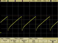
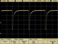
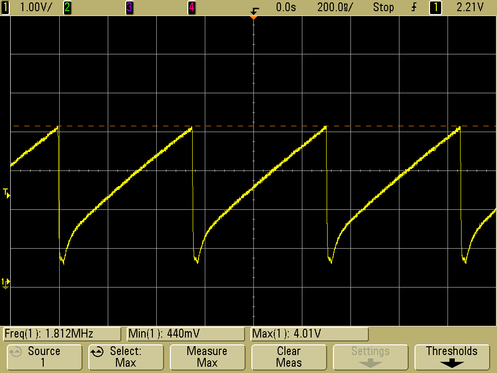
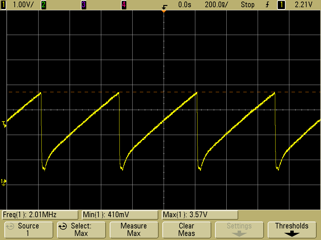
Here's the ramp waveform at 2MHz. Basically expected, except the recovery of the diode seems a bit slow.
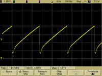
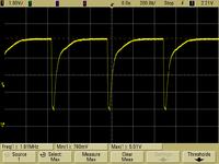
I tried lowering the clock frequency a bit. As expected, the ramp reaches a higher max voltage before being brought low. Also it looks as if the diode recovery is getting slower...
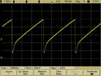
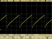
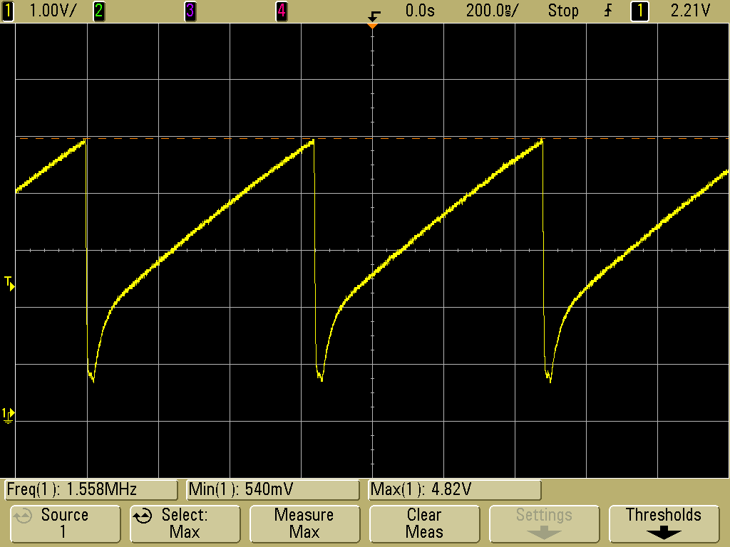
Lower the frequency a bit more to 1.56MHz, and now the max voltage takes the BJT towards saturation. But the recovery from the pulse is even more distorted now....
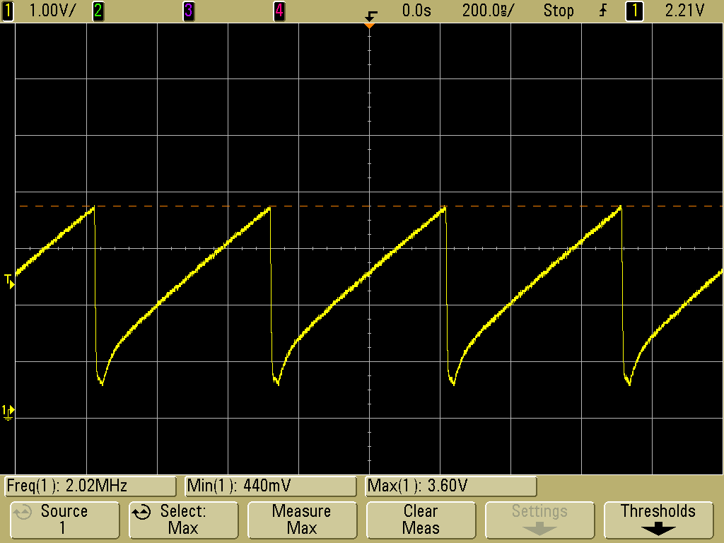
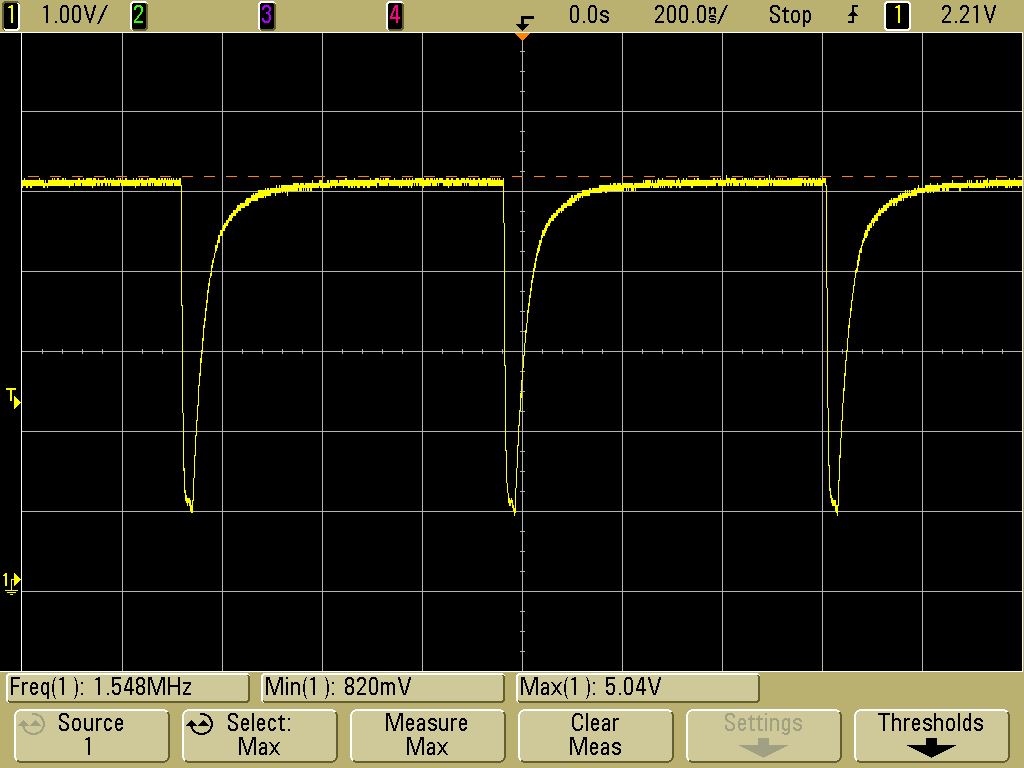
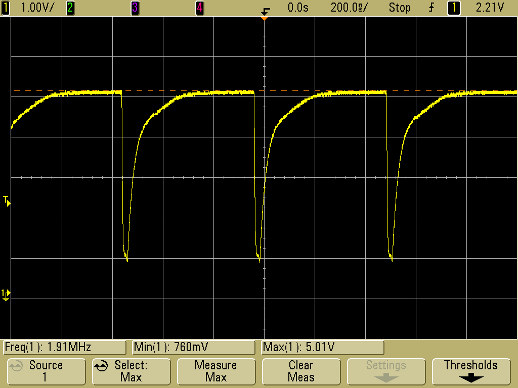
Lower the frequency a bit more to 1.54MHz, and suddenly I get this:
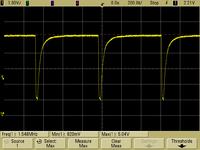
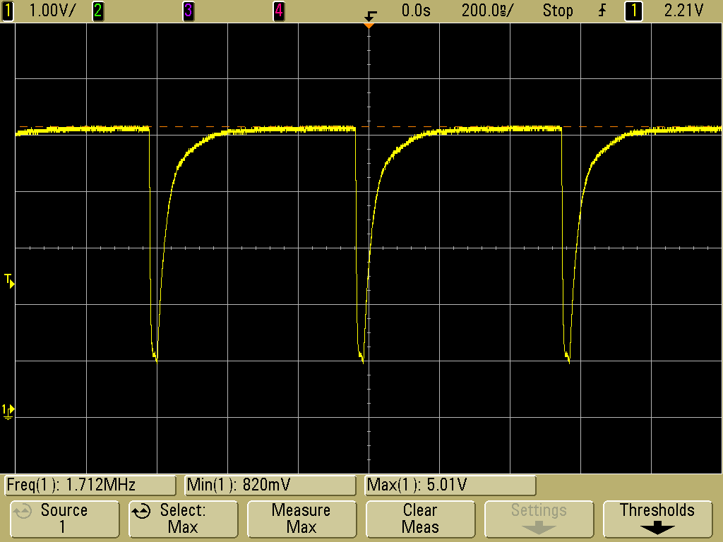
Strangely, if I increase the frequency to 1.7MHz, the waveform is still messed up:
As the frequency is further dialed up to 1.9MHz, the ramp is starting to show up a little bit again...
And at 2MHz, it suddenly snaps back to the original ramp waveform:
I've pretty much ruled out the diode as the culprit (tried different devices with no effect). It seems to be that the BJT does not like being brought out of saturation quickly. When this happens, it will conduct more strongly than normal for a hundred or so nanoseconds, causing it to snap back into saturation. This gives the circuit a sort of hysteretic behaviour.
I know BJTs have storage time, which limits limits how fast it can exit saturation when the gate current is switched off, but I never heard of something similar happening when operated when the base current is fixed while the collector is driven. But I assume it's the same phenomenon? The BJT pair I used doesn't list anything about storage time, but it is specified for use in high speed current mirrors and diff amps. So how would I pick a replacement?
I've verified that a baker clamp prevents the circuit from snapping back into saturation, but the distortion after each reset pulse is still there, which is annoying. I think finding another BJT is the only way to get rid of that....
I've made a circuit to generate a linear ramp waveform from a 5V clock. A BJT current mirror sources a constant current into a capacitor, and and the capacitor is periodically discharged through a diode, which is driven by the clock. The clock has a high duty cycle such that its low time is just 25ns. The schematic is shown below, with accurate component values.
Here's the ramp waveform at 2MHz. Basically expected, except the recovery of the diode seems a bit slow.
I tried lowering the clock frequency a bit. As expected, the ramp reaches a higher max voltage before being brought low. Also it looks as if the diode recovery is getting slower...
Lower the frequency a bit more to 1.56MHz, and now the max voltage takes the BJT towards saturation. But the recovery from the pulse is even more distorted now....
Lower the frequency a bit more to 1.54MHz, and suddenly I get this:
Strangely, if I increase the frequency to 1.7MHz, the waveform is still messed up:
As the frequency is further dialed up to 1.9MHz, the ramp is starting to show up a little bit again...
And at 2MHz, it suddenly snaps back to the original ramp waveform:
I've pretty much ruled out the diode as the culprit (tried different devices with no effect). It seems to be that the BJT does not like being brought out of saturation quickly. When this happens, it will conduct more strongly than normal for a hundred or so nanoseconds, causing it to snap back into saturation. This gives the circuit a sort of hysteretic behaviour.
I know BJTs have storage time, which limits limits how fast it can exit saturation when the gate current is switched off, but I never heard of something similar happening when operated when the base current is fixed while the collector is driven. But I assume it's the same phenomenon? The BJT pair I used doesn't list anything about storage time, but it is specified for use in high speed current mirrors and diff amps. So how would I pick a replacement?
I've verified that a baker clamp prevents the circuit from snapping back into saturation, but the distortion after each reset pulse is still there, which is annoying. I think finding another BJT is the only way to get rid of that....
Last edited:
