Continue to Site

Welcome to EDAboard.com

Welcome to our site! EDAboard.com is an international Electronics Discussion Forum focused on EDA software, circuits, schematics, books, theory, papers, asic, pld, 8051, DSP, Network, RF, Analog Design, PCB, Service Manuals... and a whole lot more! To participate you need to register. Registration is free. Click here to register now.

Crystal oscillator stability at different ouput levels, issues

Status
Not open for further replies.

neazoi

Advanced Member level 6
Joined
Jan 5, 2008
Messages
4,122
Helped
13
Reputation
26
Reaction score
15
Trophy points
1,318
Location
Greece
Activity points
36,951
Hi,
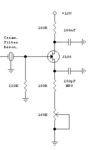
This little crystal oscillator I have designed by trial and error, uses crystals or ceramic resonators to oscillate at HF.
There ia a "hitten" capacitor formed by the internal capacitance of the gate-source of the FET.

When I set the source trimmer at extreme ends (especially at low values, max OSC gain) the oscillator changes frequency by a few 100's Hz.
I have noticed this with ceramic resonators as well as with crystals and also even when I have put a real NP0 capacitor between the gate-source.

Why is this hapenning?
What can I do to correct this, without sacrificing too much the range of the gain of the oscillator?
 

Attachments

  • Capture.PNG
    Capture.PNG
    3.3 KB · Views: 55

I suggest that you buffer the oscillator part from the amplifier part. That way you can adjust the gain without affecting the frequency.
Also what is on the other side of the crystal/resonator?
Without spending a lot of time analysing this in detail, what I suspect is happening is that you are altering the impedance as seen by the crystal. The equivalent circuit of a crystal is a capacitor, resistor and inductor in series, all in parallel with a capacitor. It has a very high Q which typically can made it very sensitive to value changes in the surrounding circuit and load. By altering the source resistance you are altering the characteristics/load and so pulling the crystal frequency.
By the way, if the values on your schematic are correct, then the trimmer resistor in the source line of the FET at 100K will swamp the 100R that it is in series with. I know that you can say that the 100R provides a minimum resistance in the source line, but unless the trimmer is right at the end of the range, then it will have very little effect.
Susan

I have already done buffering here **broken link removed** It does not change anything as far as concern the frequency pulling on the high-gain state of the oscillator.
So I tend to believe as well that it is due to the current into the crystal. This the greatest pulling exists when harmonics start to appear out of the oscillator (high-levels of uoutput signal).

Someone suggested to try a capacitor from the positive end of the pot to the ground. Say 100nF?
 

Status
Not open for further replies.

Part and Inventory Search

Welcome to EDABoard.com

Sponsor

Back
Top