Continue to Site

Welcome to EDAboard.com

Welcome to our site! EDAboard.com is an international Electronics Discussion Forum focused on EDA software, circuits, schematics, books, theory, papers, asic, pld, 8051, DSP, Network, RF, Analog Design, PCB, Service Manuals... and a whole lot more! To participate you need to register. Registration is free. Click here to register now.

switching Voltage amplifier into transcondactance amplifier

Status
Not open for further replies.

yefj

Advanced Member level 4
Joined
Sep 12, 2019
Messages
1,189
Helped
1
Reputation
2
Reaction score
3
Trophy points
38
Activity points
7,172
Hello I Have designed a Voltage amplifier ,i Have a high impedance on the input and low impedance on the out put.
amplifier plot and its Gain responce shown bellow.
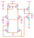
if the schematics bellow there is a transimpednce amplifier design.
How make our built amplifer to sense current?(as shown in the plt bellow?
Thanks
3.JPG

1.JPG
2.JPG
 

Connecting your voltage amplifier in transimpedance configuration should achieve what you want.

According to the gain plot (no phase response shown, unfortunately), it's questionable if you achieve sufficient phase margin for stable operation. Miller compensation may need adjustment.
 

Hello i have added miller compensation and attached the phase and amplitude_dB.
At 0dB we have 52 degree phase. so 180-52>60 so its a stable system correct?
regarding transforming it into transimpedance amplifier how could we make a feedback network so it will sense current and return voltage ,from this amplifier?
Thanks.

1.jpg
2.JPG
 

how could we make a feedback network
As already said, use the transimpedance circuit in post#1.

In the bode plot, 52 degree is your phase margin, slightly smaller than 60 but still stable. Feedback factor in the transimpedance circuit differs from 1, depending on the source capacitance and Cf. Thus phase margin should be determined and possibly corrected in the final application circuit.
 

It is daytime here. Your schematic is a negative image that is black with a few tiny electronic parts too far apart making them so small.
 

Hello,regarding the simple topology shown bellow, i need to make it work by the genenal feedback theory.
I have an OPAMP with very large input impedance and very small output impedance.
as shown in the plot bellow
My transimpedance amplifier need to have small impedance in the input and very small output impedance.
the feed back network has to be with large imprdance both on input and out put.

How can plan my feed back network to be with both large input and out put impedance,its just a capacitor with resistor in parralel ?
What could be done to ensure that we will get input/output impedances of the feedback and amplifier by the general theory of two port feedback?
Thanks.

1.JPG
2.jpg
3.JPG
 

I do not liked seeing a negative image with no contrast so I made the schematic a positive with more contrast and uncrossed a few wires.
Cropping it made the parts closer together. When I went to enlarge it I found it to be a fuzzy Jpeg instead of a clear PNG.
 

Attachments

  • transconductance amplifier.png
    transconductance amplifier.png
    55.5 KB · Views: 175
  • Like
Reactions: FvM

    FvM

    Points: 2
    Helpful Answer Positive Rating
yefj said:
I have an OPAMP with very large input impedance and very small output impedance.
Not actually very small output impedance. Your two stage amplifier is missing a dedicated output buffer. If we don't consider the miller capacitor, the output is rather a current than a voltage source. Nevertheless you'll achieve a low closed loop output impedance by working of feedback.

yefj said:
My transimpedance amplifier need to have small impedance in the input and very small output impedance.
the feed back network has to be with large impedance both on input and out put.

It's unrealistic to ignore the feedback network impedance in your circuit. Respectively the calculations in post #6 are not appropriate.

The feedback network input and output impedance is simply Rf||Cf. When used with a CMOS OP, Rf will dominate in the low frequency range, at high frequencies, Cin will play a role, thus the total open loop input node impedance is Rf||Cf||Cin. Similarly, Rf||Cf must be also considered when calculating the output node impedance, particularly because your OP has a relative large output impedance.

I like the treatise in Gray, Hurst, Lewis, Meyer, Analysis and Design of Analog Integrated Circuits. In 5th edition at page 563ff (paragraph 8.5.1 Shunt-Shunt Feedback).

- - - Updated - - -

Audioguru said:
I do not liked seeing a negative image with no contrast so I made the schematic a positive with more contrast and uncrossed a few wires.
Cropping it made the parts closer together. When I went to enlarge it I found it to be a fuzzy Jpeg instead of a clear PNG.
The "nighttime view" is the default display scheme of popular analog IC design tools like Cadence Virtuoso, combined with probably non optimal user parameters. In the present schematic, there isn't much information besides the basic amplifier topology, it's not worth to put much effort in decoding it.
 
I believe you, the best circuit for trans impedance amplifier will be CMFB opamp and not the one which you have mentioned. The circuit which you have used will be good only for input and output voltage (if you have load connected at output, either CL or RL). Transimpedance uses resistor at its input which will give lower impedance, despite having the same differential amplifier.
To have low impedance at input you need to use inverting amplifier design, which has resistor feeback loop so that current can flow,( The differential amplifier will remain the same, except that you will have CMFB based design which will dynamically set the feedback ). Check in Gray Huset book , or there is a lecture series on how do design it. If you are novice, lecture flow will be difficult to understand. (Lecture 39-41 will help you for this).

- - - Updated - - -

https://nptel.ac.in/courses/117/106/117106030/
this is the link for CMFB design
 

Status
Not open for further replies.

Similar threads

Part and Inventory Search

Welcome to EDABoard.com

Sponsor

Back
Top