Continue to Site

Welcome to EDAboard.com

Welcome to our site! EDAboard.com is an international Electronics Discussion Forum focused on EDA software, circuits, schematics, books, theory, papers, asic, pld, 8051, DSP, Network, RF, Analog Design, PCB, Service Manuals... and a whole lot more! To participate you need to register. Registration is free. Click here to register now.

Amplifier Circuit for Thermopile with Thermistor for Cold-junction compensation

Status
Not open for further replies.

eepty

Full Member level 2
Joined
Oct 21, 2005
Messages
143
Helped
2
Reputation
4
Reaction score
2
Trophy points
1,298
Activity points
2,611
How to calculate temperature resistance for Ni-RTD?

I would like to build a circuit to read the signal from a thermopile temperature sensor which has build-in RTD temperature sensor for cold-junction compensation. The datasheet of the sensor is here. I need to know the resistance value of the built-in Ni-RTD at some particular temperature to build the circuit. I search the web to check how can I calculate the resistance value but all I could find is the formula for a platinum RTD. Could you guide me how to calculate the resistance value for a Ni-RTD?

My target temperature is from 0-85C only.

Thank you very much.
 

Re: How to calculate temperature resistance for Ni-RTD?

Polynomial of a nickel resistor in accordance with DIN 43760:
Code:
R(ϑ) = R0 x (1 + 5.481x10^-3xϑ + 6.650x10^-6xϑ^2 + 2.805x10^-11xϑ^4 + 2.000x10^-17xϑ^6)

For the limited temperature range, you probably want to calculate with linear TK of 6180 ppm/K.

- - - Updated - - -

P.S.: I see that the TK is already given in the datasheet, so no additional info needed, actually. If you see the tolerance specification, it should be clear that the accuracy is limited anyway.
Code:
R(ϑ) = 1000 x (1 + 6.18x10^-3xϑ)
 
  • Like
Reactions: eepty

    eepty

    Points: 2
    Helpful Answer Positive Rating
I would like to build a circuit for reading temperature from a thermopile temperature sensor. I found this application reference for the circuit (page 6, Single power supply type with thermistor). However I do not understand how to calculate the resistance value (Ra, Rb, Rc).

At step 2, it requires:
1) Measure the thermopile detector output voltage (Voutmin) at Tmax.
2) Measure the thermopile detector output voltage (Voutmax) at Tmin.

What does that mean? How can I measure the thermopile output voltage before I build the circuit?

Thank you very much
 

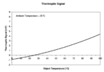
I think the compensation circuit output should have the same characteristic as the sensor output, presuming the sensor output is zero when object temperature is equal to sensor temperature.

TP signal.PNG
 

Status
Not open for further replies.

Similar threads

Part and Inventory Search

Welcome to EDABoard.com

Sponsor

Back
Top