Continue to Site

Welcome to EDAboard.com

Welcome to our site! EDAboard.com is an international Electronics Discussion Forum focused on EDA software, circuits, schematics, books, theory, papers, asic, pld, 8051, DSP, Network, RF, Analog Design, PCB, Service Manuals... and a whole lot more! To participate you need to register. Registration is free. Click here to register now.

Distance between air coil inductors

Status
Not open for further replies.

dolgaleb

Junior Member level 3
Joined
Nov 9, 2008
Messages
31
Helped
0
Reputation
0
Reaction score
1
Trophy points
1,286
Activity points
1,574
How close can I place two inductors in a 4 pole 1 GHz filter. The longest inductor's length is 2.8 mm. I ask the question because I will not place them perpendicular to each other.

Evelyn
 

The answer is pretty implicit because physical distances play very important role here and they are unfortunately vary by board to board.
Finally you will have to tune each coil.. it's clear.Distance should be large as much as possible ...there is no rule of thumb about it.
 

Perpendicular air coils have ideally zero coupling due to symmetry properties. There's however also inductive coupling to traces and capacitive coupling. Finally the answer depends on the filter characteristic and e.g. intended stop band attenuation.
 

Smaller gaps (high coupling) between filter resonators decrease the loaded-Q of the resonators.
This will affect the performances of the filter as: in-band ripple and insertion loss, and out-band rejection.
Usually in a filter design, the first and the last resonators (input and output) have tighter coupling (smaller gaps) with the adjacent resonators.
When reaching the lowest limits of these gaps, also have to take in consideration the voltages (powers) going into to the filter.
 

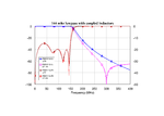
Coupled coils can also be used to "improve" the stopband of a low pass filter.
Here is a (realized) example of a 144 MHz low pass filter (n=7). Two coils are slightly coupled (k<0.1) and thus create an attenuation pole in the stopband.
But it makes sense to test first in the simulation whether such an effect can really be used in a reasonable way (tunability, reproducibility).
144 mhz lowpass with coupled inductors.png
 

Status
Not open for further replies.

Part and Inventory Search

Welcome to EDABoard.com

Sponsor

Back
Top