2bengg
Junior Member level 3
Hello.
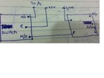
i am trying control a relay directly with a switch.
there is also a connection to the pin of a micro controller. This is to detect if the relay is operating or not.
when the common and N/C of the switch are connected, the micro controller can read the voltage as 5 volts and as a result detect that relay is OFF.
however when the switch is operated, ie common and N/O of the switch are connected, the input of the micro controller is left floating.
while it will probably work most of the time, there is a chance of detecting false positive or false negative.
what can i do to improve this ?
i cannot have the switch connected to a micro controller and have the micro controller turn the relay on, because the micro controller is other wise generally occupied and i need the relay to switch ON as soon as the switch is pressed.
suggestions ?
i am trying control a relay directly with a switch.

there is also a connection to the pin of a micro controller. This is to detect if the relay is operating or not.
when the common and N/C of the switch are connected, the micro controller can read the voltage as 5 volts and as a result detect that relay is OFF.
however when the switch is operated, ie common and N/O of the switch are connected, the input of the micro controller is left floating.
while it will probably work most of the time, there is a chance of detecting false positive or false negative.
what can i do to improve this ?
i cannot have the switch connected to a micro controller and have the micro controller turn the relay on, because the micro controller is other wise generally occupied and i need the relay to switch ON as soon as the switch is pressed.
suggestions ?
