Continue to Site

Welcome to EDAboard.com

Welcome to our site! EDAboard.com is an international Electronics Discussion Forum focused on EDA software, circuits, schematics, books, theory, papers, asic, pld, 8051, DSP, Network, RF, Analog Design, PCB, Service Manuals... and a whole lot more! To participate you need to register. Registration is free. Click here to register now.

[SOLVED] DC voltage isolation

Status
Not open for further replies.

flote21

Advanced Member level 1
Joined
Jan 22, 2014
Messages
411
Helped
1
Reputation
2
Reaction score
3
Trophy points
1,298
Activity points
5,595
Hi!

I need to accomplish an isolation of the reference GND of the 24Vdc power supply. The idea is not use a DCDC 1:1 converter because it increases a lot the price of the project. Is there anyway to achieve this target?:

IsoBlock.jpg

Thanks in advance!

Greetings
 

Hi,

Not sure if galvanic isolation can do that.
 
Hi,

Isolated DC in / DC out .... but no DCDC converter?
What's your idea?

A solar cell driven by a halogen lamp?

Klaus
 
Not sure. I was wondering about that. But you are right...I need to use a DcDc converter to get galvanic isolation...maybe I can find a cheap part to do it..
Thanks a lot
Greetings
 

Hi,

which amount of power do you want to transmit and what would be your cost limit?

greets
 

Hi!
Not too much power. I just want to supply three relays. Maybe 100 mA maximum..
Greetings
 

Hi,

I just want to supply three relays
Relays are already isolated. Why another isolated power supply?

Klaus
 

Hi!

Yes. But I am using the same voltage to control the relay and to give its output:


relay.png

I would like to isolate the Green part from the Black part of the image.

Greetings
 

Someting coming into my mind would be a switched capacitor approach, as a transformer based circuitry is usually more expensive.
Maybe a circutry based on the 555 timer IC would work for you [1], as the costs of the 555 are below $1. Of course you would have to adjust the supply voltage of the 555.

[1] https://www.edn.com/charge-pump-topology-doubles-voltage-breaks-dc-path/

greets
 

Hi,

I´m confused.
I would like to isolate the Green part from the Black part of the image.
* the green part basically is just a diode. How/why do you want to isolate the diode. What will be the function of an isolated diode?
* the black part is named "isolated" but it is not isolated.

I just want to supply three relays.
I see only one Relay.
And maybe consider not to isolate the drive side of the relay but the load (conatact) side of the relay.


.. and all the resistors in the black box are "0R" --> doesn´t this short circuit the 24V?

Klaus
 

I assume the green marked 24 V supply as well as the left ground (source of the MOST) should be isolated. The diode is a flyback one.
Further, it seems the four resistors in the black box are used to choose between GND and 24 V, so two of them have to be desoldered to avoid a short circuit (and set the chosen potential). One should mark those with DNI (Do Not Install) or TBD (To Be Defined) do avoid a failure during assemmbly (performed by an other person).

If the GND on the left side would be a different ground potential (different symbol), the LED has to be connected to the "right-side / black-box" ground, otherwise it is floating and des not light up.

That's how I interpreted the schematic ;-).

greets
 

Hi!

I will try it to explain it a bit better.

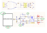
In the next pic I have +24V comming from the connector "J?". From +24Vdc I get +-15Vdc through an isolated DCDC converter. Therefore I should have isolated "GNDs" for 24V and +-15V.

But as you can see the other pic, the output stage of the signal conditioning circuit, integrated by the relay and the NMOS, is using 24V to generate low level (0V) or high level (+24V) according to the previous control stage. So there is a GNDs conflict, because at the output stage I am joining isolated GND from the DCDC converter with the reference GND of +24V. So my initial question was it there was anyway to isolate the reference 24V GND from the isolated DCDC GND having into account the proposal output stage configuration.

Explanation.png

Thanks a lot

Greetings
 

Hi,

I´m too dumb to understand.

I still don´t know
* whether the new schematic is your current version or your desired solution.
* why there is now +/-15V (never mentioned before)
* Why you say you want it isolated but your schematic shows the opposite. (If you want to have different GNDs then use different GND symbols.. Ah, I now realize you changed the GND symbol... but why all of them. All makes no sense to me.)
* What´s the use of "R?" (trick question)
* Do you really want to drive Q? with +/-15V?

because at the output stage I am joining isolated GND from the DCDC converter with the reference GND of +24V.
You may join them if you like. It won´t hurt.
But I thought you wanted it isolated.

I hve no idea what´s the goal of this all..


Klaus
 
Now you lost me too :lol:.

Why aren't you using a relay with a rated switching voltage of 15 VDC? The swichted load voltage is typically much HIGHER than the rated coil-voltage (above 100 V), and is not the same as the coil-voltage.

greets
 
Hi!!

dont worry! it was my problem because I did not explain it very well at the beginning.

The schematic of my last post is my current design. I mean, as far as i dont have anyway to isolate the GNDs from +24Vdc and +-15Vdc, I used the the next NO ISOLATED approach:

schematic2.png

There was a mistake in my previous schematic. The B-E resistors is not mounted:

schematic.png

The output stage of the black box "CONTROL NMOS STAGE is a comparator. I use a NMOS to drive the 24Vdc Relay. Maybe the easiest solution is to dirve the relay directly with the ouput of the comparator:

shematic3.png

Howover I am wondering if the comparator has enouth "strength" to drive the relay...Other way I can power the NMOS with +15Vdc and my non isolation problem will be solved. I just need to find a relay with the nex part number: G5V-1-T90-15V

Note:I tried to simulate the next approach, and at the output of the relay, I never got 0V.

realy.png

Greetings
 
Last edited:

Still don't getting the whole picture, but your current relay type states a 150 mW nominal coil power consumption. Thus, a 15 V version ( 15 V version is not available!) would source a current of 10 mA, which is the minimum stated sink current if supplied by ±15 V. See note 2 in the datasheet regarding heat sink, the package has a themal resistance of θ_JA = 250°C/W! Have also a look on the figures titeled "Output Low Voltage vs Sink Current" and "Output Sinking Currentvs Total Supply Voltage".

Use a NMOST in LOW SIDE CONFIGURATION to simulate the intended operation. The simulation makes no sense to me.

greets

- - - Updated - - -

BTW: The LT1716 is available in LTspice XVII
 

Hi,

I do not understand what you're really asking though.

I think you are saying that your +/-15V is floating and so should not share the same ground (in your circuit) with your 24V. If so, I would suggest you drive the relay coil with your 15V and then connect the contact side of the relay to 24V. The LED end and the jumper end should be connected to the 24V GND. The MOSFET source terminal should be connected to the 15V GND.

I hope that is what you asked about.
 
I think you are saying that your +/-15V is floating and so should not share the same ground (in your circuit) with your 24V.

That was exaclty my problem!!!

If so, I would suggest you drive the relay coil with your 15V and then connect the contact side of the relay to 24V. The LED end and the jumper end should be connected to the 24V GND. The MOSFET source terminal should be connected to the 15V GND.

I hope that is what you asked about.

I like this solution, but there are not to many relays with coil voltage of 15Vdc. Therefore I am going to use LDO to get 12Vdc from +15Vdc of the isolated DCDC converter to supply the relay coil...

Thanks a lot!
 

Hi,

you might also use a 12 V zener diode in parallel to your relay. As the expected current is constant, the required series resistor can easily be determined. Keep the voltage drop at the open drain output of your comparator in mind.
Further, the zener diode also acts as flyback diode.

greets

- - - Updated - - -

You also may operate a relay with a rated coil-voltage of 12 V with 15 V e.g. for [1] the maximum coil-voltage is 170 % the rated voltage.
Thus your maximum voltage for the 12 V version would be 12 V • 1.7 = 20.4 V.

[1] https://omronfs.omron.com/en_US/ecb/products/pdf/en-g5le.pdf

greets
 

Status
Not open for further replies.

Part and Inventory Search

Welcome to EDABoard.com

Sponsor

Back
Top