Continue to Site

Welcome to EDAboard.com

Welcome to our site! EDAboard.com is an international Electronics Discussion Forum focused on EDA software, circuits, schematics, books, theory, papers, asic, pld, 8051, DSP, Network, RF, Analog Design, PCB, Service Manuals... and a whole lot more! To participate you need to register. Registration is free. Click here to register now.

How to test this integrated Regulated PWM " SG3524N " ? thanks

Status
Not open for further replies.

dineshdeshmuk

Full Member level 5
Joined
Sep 12, 2011
Messages
285
Helped
18
Reputation
36
Reaction score
18
Trophy points
1,298
Activity points
3,131
How to test this integrated Regulated PWM " SG3524N " ?

What does it mean by " shutdown ", " Current Lim + " & " Current Lim - " ?

why are they used ?

thanks
 

How to test this integrated Regulated PWM " SG3524N " ?

What does it mean by " shutdown ", " Current Lim + " & " Current Lim - " ?

why are they used ?

thanks
 

How to test this integrated Regulated PWM " SG3524N " ?
What does it mean by " shutdown ", " Current Lim + " & " Current Lim - " ?
why are they used ?

SG3524
REGULATING PULSE WIDTH MODULATORS
https://www.st.com/internet/com/TECHNICAL_RESOURCES/TECHNICAL_LITERATURE/DATASHEET/CD00000117.pdf

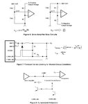
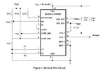
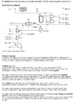
Look these pictures and read text carefully,
you should be able to make open loop test circuit
oscillator calculations formula is there for Rt & Ct
and block diagram show what to measure and where.
Everything you need has been told there.

Hey Man , What else you need..............

Can this SG3524 be used as a gate driver for a power Mosfet ?

what should be the result or output of the open loop test ? (I don't have the oscilloscope)

thanks awfully
 
Can this SG3524 be used as a gate driver for a power Mosfet ?

Yes. Here is two examples................

http://www.chinaicmart.com/uploadfile/ic-circuit/2009628212138296.gif

http://www.eleccircuit.com/wp-content/uploads/2008/07/12vdc-to-37v-dc-converter-by-sg3524.jpg

what should be the result or output of the open loop test ? (I don't have the oscilloscope)

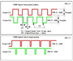
You need 2 channel oscilloscope to check output signals in pins 12 & 13 .
You should see some signals between pict.1 and pict.2 ( output low pulse is modulated [PWM] and varies depending on control )

PWM Output IcSGxxx.jpg
 
thanks
KAK .......

This IC with P channel HEX Power Mosfet (IRF 9520) + few zeners + some resistors + step down transformer (converting 110 V to almost 40 V) + LM 358 N (LOW POWER DUAL BIPOLAR OP-AMPS) ....... are connected in a circuit to produce different voltage supplies (different outputs) 24 VDC, 10 VDC etc .....

Can you tell me how the circuit is operating ? OR what actually is happening in the circuit ?

without any schematic, how to understand or read which component is connected to which component & to which pin no. ?

thanks
 

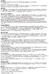
Datasheet rewritten...................

sg3524_block_diag_text_01.jpg
sg3524_block_diag_text_02.jpg
sg3524_Fig6_7_8.jpg
sg3524_general_test_pict_rr.jpg

Pict`s & text´s : Texas Instruments SLVS077D – APRIL 1977 – REVISED FEBRUARY 2003
 
Status
Not open for further replies.

Similar threads

Part and Inventory Search

Welcome to EDABoard.com

Sponsor

Back
Top