Continue to Site

Welcome to EDAboard.com

Welcome to our site! EDAboard.com is an international Electronics Discussion Forum focused on EDA software, circuits, schematics, books, theory, papers, asic, pld, 8051, DSP, Network, RF, Analog Design, PCB, Service Manuals... and a whole lot more! To participate you need to register. Registration is free. Click here to register now.

What is load cell ? How it works ? thanks

Status
Not open for further replies.
I could not find any documents or information about this machine
in order to be able to answer questions,
I need to know the machine structure and see the control block diagram
can we change the frequency controlling method of the inverter(s) in such a way that there's no problem in web tensioning process ?
Do not alter the factory settings, because all the control parameters are dependent on
one another.

This is usually used tension control principle..............
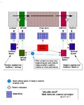
WebTensionPrinciple_01.jpg

Tension control in print units depends on manufacturer system design,
it can be done via tension measure before or after print units and
control decrease infeed speed or increase outfeed speed.
( Can´t say without machine tech. documents )

Also the main motor is starting when the speedometer on the digital screen shows the speed of 5 m/min , although it was starting as the speed increased from 0 to 1 m/min , why is it so ?

How the speed is measured, have you any instructions for calibration the speed measuring system.
( Wrong speed feedback can cause the problem. )

Motor VFD`s principle of operation is chosen by the manufacturer and matched to the other components of the control system.
If changing them , can lead to severe problems.

KAK
 
Last edited:
You find the differencies by looking these pictures........
Control methods
–Open loop algorithms
–Closed loop algorithms

View attachment 64313
View attachment 64312
View attachment 64311
View attachment 64310

Here is all the text & pictures ..............
Very good seminar presentation papers

Implementing Embedded Speed Control for AC Induction Motors
http://am.renesas.com/media/products/mpumcu/child_folder/Renesas_Jani_Seminar.pdf

Referring to these figures, that you provided :

kindly, answer following questions please :

1) constant torque control : indirect ? (in v/f control)
2) What is dynamic torque control ?
3) What is DCCT ?
4) closed loop with estimation , what do you mean by estimation ?
5) what is OSCD & OSCD Method ?
6) difference between constant torque control & torque control ?

you tell that vector control is best of the all for : accuracy, constant torque control, torque control , Am i right ?

thanks

---------- Post added at 19:48 ---------- Previous post was at 19:11 ----------

I could not find any documents or information about this machine
in order to be able to answer questions,
I need to know the machine structure and see the control block diagram

Do not alter the factory settings, because all the control parameters are dependent on
one another.

This is usually used tension control principle..............
View attachment 64598

Tension control in print units depends on manufacturer system design,
it can be done via tension measure before or after print units and
control decrease infeed speed or increase outfeed speed.
( Can´t say without machine tech. documents )


How the speed is measured, have you any instructions for calibration the speed measuring system.
( Wrong speed feedback can cause the problem. )

Motor VFD`s principle of operation is chosen by the manufacturer and matched to the other components of the control system.
If changing them , can lead to severe problems.

KAK

what does it mean by ?
How the speed is measured, have you any instructions for calibration the speed measuring system.

do you want to ask that do i have a instruction manual to calibrate the speed measuring system ?

thanks
 

1) constant torque control : indirect ? (in v/f control)
2) What is dynamic torque control ?
Direct torque control - Wikipedia, the free encyclopedia

3) What is DCCT ?
DCCT = DC current transducer & ACCT = AC current transducer

4) closed loop with estimation , what do you mean by estimation ?
control has no real current- / speed- feedback ,
closed loop is estimated ie. calculated approximations is used instead of
feedback measurement values.

5) what is OSCD & OSCD Method ?
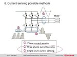
One Shunt Current Detection or Single Shunt Current Detection (OSCD or SSCD)

VFD_Curr_Sens_Methods.jpg

6) difference between constant torque control & torque control ?
Generally we can say that , fans and centrifugal pumps are variable torque loads.
At 50% speed the torque is 50% so the power needed is only 25%.

For example , a conveyor takes the same torque whether it is running 0.1 m/s or 10 m/s,
so at 50% speed it needs full torque at 50% power.

------------------------------------------------------

Because I don´t have any tech. or service documents for this machine,
it is "mission impossible" to tell you what to do.


So I asked , do you have a instruction manual to calibrate the speed measuring system ?
and do you have any technical and maintenance manuals of the machine at all.
 
what are DCCT = DC current transducer & ACCT = AC current transducer ?
where are these used ?
types & examples of these ?

thanks
 
What are current transducers
**broken link removed**

**broken link removed**

Linear output Hall effect transducer AC/DC
**broken link removed**

DC Current Transducer example
**broken link removed**

AC Current Transducer example
**broken link removed**

where are these used ?
For example >> Look post #52 : Pictures 2, 3 & 4
 
Last edited:
  • Like
Reactions: munzir

    munzir

    Points: 2
    Helpful Answer Positive Rating
  • Like
Reactions: munzir

    munzir

    Points: 2
    Helpful Answer Positive Rating
I could not find any documents or information about this machine
in order to be able to answer questions,
I need to know the machine structure and see the control block diagram

Do not alter the factory settings, because all the control parameters are dependent on
one another.

This is usually used tension control principle..............
View attachment 64598

Tension control in print units depends on manufacturer system design,
it can be done via tension measure before or after print units and
control decrease infeed speed or increase outfeed speed.
( Can´t say without machine tech. documents )


How the speed is measured, have you any instructions for calibration the speed measuring system.
( Wrong speed feedback can cause the problem. )

Motor VFD`s principle of operation is chosen by the manufacturer and matched to the other components of the control system.
If changing them , can lead to severe problems.

KAK

Here it is for you KAK: (especially for you but others also comment on that)

https://obrazki.elektroda.pl/30_1322505143.jpg
https://obrazki.elektroda.pl/95_1322505144.jpg


Kindly, now explain me the process please
thanks
 
  • Like
Reactions: munzir

    munzir

    Points: 2
    Helpful Answer Positive Rating
You diagrams show, that all control operations are performed by the S7-200 CPU226 and it's associated analog input and output modules. You'll need to read the PLC program to understand the details. The raw PLC program may be password protected aigainst readout.
 
Direct torque control - Wikipedia, the free encyclopedia


DCCT = DC current transducer & ACCT = AC current transducer


control has no real current- / speed- feedback ,
closed loop is estimated ie. calculated approximations is used instead of
feedback measurement values.


One Shunt Current Detection or Single Shunt Current Detection (OSCD or SSCD)

View attachment 64751


Generally we can say that , fans and centrifugal pumps are variable torque loads.
At 50% speed the torque is 50% so the power needed is only 25%.

For example , a conveyor takes the same torque whether it is running 0.1 m/s or 10 m/s,
so at 50% speed it needs full torque at 50% power.

------------------------------------------------------

Because I don´t have any tech. or service documents for this machine,
it is "mission impossible" to tell you what to do.


So I asked , do you have a instruction manual to calibrate the speed measuring system ?
and do you have any technical and maintenance manuals of the machine at all.

Referring to the diagrams , what is mean by " constant torque control indirectly " ?
&
What is mean by " dynamic torque control indirectly " ?

thanks
 
Schematics show only
S7-200 CPU 226
and analog input and output modules

Digital inputs from
-buttons 14pcs
-relays, contactors 3pcs
-limit switches 2pcs

Digital outputs to
-relays, contactors 14pcs
-lamps 2pcs
-alarm bell
-press roll 6pcs
-heat blow 6pcs

Four analog inputs
from potentiometer sensor for
-unwind
-infeed
-outfeed
-rewind

Six analog outputs for
-main motor
-infeed motor
-outfeed motor
-unwind A motor
-unwind B motor
-rewind A motor
-rewind B motor

Communication port1

as FvM wrote

Without PLC program list , we can´t say anything
about logic and functions between inputs and outputs.

In addition, we should know the machine mechanical design
and placement of sensors and motors locations in web-line.
(Exact how the controlled web goes through rolls,
locations of the rolls measured with potentiometers
locations of the rolls driven by controlled motors )

what is mean by " constant torque control indirectly " ?
&
What is mean by " dynamic torque control indirectly " ?

Please read through this document carefully
AC Induction Motor Fundamentals

Read this particularly careful.
CONTROL TECHNIQUES
Various speed control techniques implemented by
modern-age VFD are mainly classified in the following
three categories:
• Scalar Control (V/f Control)
• Vector Control (Indirect Torque Control)
• Direct Torque Control (DTC)

pages 19...21

https://ww1.microchip.com/downloads/en/appnotes/00887a.pdf

KAK
 
Last edited:
Schematics show only
S7-200 CPU 226
and analog input and output modules

Digital inputs from
-buttons 14pcs
-relays, contactors 3pcs
-limit switches 2pcs

Digital outputs to
-relays, contactors 14pcs
-lamps 2pcs
-alarm bell
-press roll 6pcs
-heat blow 6pcs

Four analog inputs
from potentiometer sensor for
-unwind
-infeed
-outfeed
-rewind

Six analog outputs for
-main motor
-infeed motor
-outfeed motor
-unwind A motor
-unwind B motor
-rewind A motor
-rewind B motor

Communication port1

as FvM wrote

Without PLC program list , we can´t say anything
about logic and functions between inputs and outputs.

In addition, we should know the machine mechanical design
and placement of sensors and motors locations in web-line.
(Exact how the controlled web goes through rolls,
locations of the rolls measured with potentiometers
locations of the rolls driven by controlled motors )


Please read through this document carefully
AC Induction Motor Fundamentals

Read this particularly careful.
CONTROL TECHNIQUES
Various speed control techniques implemented by
modern-age VFD are mainly classified in the following
three categories:
• Scalar Control (V/f Control)
• Vector Control (Indirect Torque Control)
• Direct Torque Control (DTC)

pages 19...21

https://ww1.microchip.com/downloads/en/appnotes/00887a.pdf

KAK

For which extended module are you referring to ?

Digital inputs from
-buttons 14pcs
-relays, contactors 3pcs
-limit switches 2pcs

For which extended module are you referring ?

Digital outputs to
-relays, contactors 14pcs
-lamps 2pcs
-alarm bell
-press roll 6pcs
-heat blow 6pcs

For which extended module are you referring to ?

Four analog inputs
from potentiometer sensor for
-unwind
-infeed
-outfeed
-rewind

For which extended module are you referring ?

Six analog outputs for
-main motor
-infeed motor
-outfeed motor
-unwind A motor
-unwind B motor
-rewind A motor
-rewind B motor
 
  • Like
Reactions: munzir

    munzir

    Points: 2
    Helpful Answer Positive Rating
kak111 isn't but retelling the signal names from your schematic. In addition you need to know, that EM232 is analog output and EM235 analog input module etc., just a quick look into the S7-200 catalog.
 
  • Like
Reactions: munzir

    munzir

    Points: 2
    Helpful Answer Positive Rating
  • Like
Reactions: munzir

    munzir

    Points: 2
    Helpful Answer Positive Rating
kak111 isn't but retelling the signal names from your schematic. In addition you need to know, that EM232 is analog output and EM235 analog input module etc., just a quick look into the S7-200 catalog.

FvM kindly provide me the required link ?

---------- Post added at 06:48 ---------- Previous post was at 06:47 ----------

Have you not read your own attachments ,
all have been told there (post #68).

Additional info
Micro PLC SIMATIC S7-200 for less complex automation tasks - Programmable logic controllers from Siemens

kindly just name these ?
 
Search for "S7-200 System Manual" at **broken link removed**
 
kindly just name these ?

All this information found in post #68 attached diagrams........
and all the wirings of the components you find there


Digital inputs to
Central processing unit CPU226
(module marked as E1 in circuit diagram )
inputs I0.0...I2.7
from
-buttons 14pcs
-relays, contactors 2pcs
-limit switches 2pcs

Digital outputs from
Central processing unit CPU226
(module marked as E1 in circuit diagram )
outputs Q0.0...Q1.7
to
-relays, contactors 13pcs
-lamps 2pcs
-alarm bell

Digital outputs from
digital output module EM 222
(module marked as E5 in circuit diagram )
outputs Q2.0...Q2.7
to
-press roll 6pcs

Digital outputs from
digital output module EM 222
(module marked as E6 in circuit diagram )
outputs Q3.0...Q3.7
to
-heat blow 6pcs

Four analog inputs to
EM 235 analog input/output module
(module marked as E1 in circuit diagram )
inputs AIW0...AIW7 (A,B,C,D)
from potentiometer sensor for
-unwind
-infeed
-outfeed
-rewind

Two analog outputs from
EM 232 analog output module
(module marked as E2 in circuit diagram )
outputs AC1 , AC2
to
-main motor
-infeed motor

Two analog outputs from
EM 232 analog output module
(module marked as E3 in circuit diagram )
outputs AC3 , AC4
to
-outfeed motor
-unwind A motor

Two analog outputs from
EM 232 analog output module
(module marked as E4 in circuit diagram )
outputs AC5 , AC6
to
-unwind B motor
-rewind A motor

One analog output from
EM 235 analog input/output module
(module marked as E1 in circuit diagram )
output AC7
to
-rewind B motor


Overviews and technical spec´s for all these modules you find here..........
**broken link removed**
 
Last edited:
https://obrazki.elektroda.pl/95_1322505144.jpg


Referring to the above image :

the last EM235 (E1) PLC module has the input of all the four potentiometric sensors and the output is going to the Rewind motor B , it means that whenever there's a problem in the alignment of the swing arm then there has to be the problem in the Rewinding B motor, Am i right ?

thanks (esp. KAK)
 

the last EM235 (E1) PLC module has the input of all the four potentiometric sensors and the output is going to the Rewind motor B ,
it means that whenever there's a problem in the alignment of the swing arm then there has to be the problem in the Rewinding B motor, Am i right ?

No.

Each output- and input-data are fed via I/O circuits and bus to CPU and processed there.
I/O modules only match "outer world" signals to CPU , data is not processed or calculated there.
Each input and output has individual name in plc program
and each I / O is addressed to CPU separately.
(For ex. I0.5 , Q2.3, etc. or Mnemonic name in program "start_switch_A" ," motor2_contactor", etc.)

The functions to be carried out and processed (calculated) between inputs and outputs
only depends on the PLC program.


(For ex., digital signals are processed by logical functions,
analogue signals calculated by mathematical functions, comparisons, etc.)


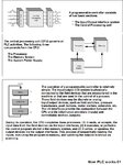
A PLC has the structure of a computer.
The function is stored as a program.
Usually a PLC consists of the following components:

Power supply (PS)
Centrol processor unit (CPU)
Modules for digital inputs and outputs
Internal bus system

In addition, modules can also be integrated in a PLC for analog inputs and outputs
(analog processing), regulator, counter and modules for positioning.

PLC is built for various requirements, either in a modular design or as a compact device.

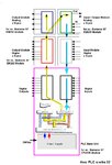
Modular PLC
At a modular constructed PLC are individual components like power supply, CPU, input-
and output-modules, special modules etc. combined and connected.
Modular PLC's are available for middle to high level of power range for an automation solution.
Depending on the requirements they can tuned exactly for the required control task.
In addition the modular control systems has the advantage, that if a module has a defect,
such as digital output module, in this case only the defect module has to be replaced and not the total PLC.

Each individual component will connected with each other by the rear wall bus with bus connector.
So the connection for data exchange between CPU and the modules are created.

The internal paths along which the digital signals flow within the PLC are called busses.
The system has four busses:
- The CPU uses the data bus for sending data between the different elements,
- The address bus to send the addresses of locations for accessing stored data,
- The control bus for signals relating to internal control actions,
- The system bus is used for communications between the I/O ports and the I/O unit

HowPLCworks01.jpg

HowPLCworks02.jpg

KAK
 
Do you mean to say that these inputs A+ , A- , B+ , B- , C+ , C- , D+ & D- would be going into the CPU 226 as the input of CPU 226 and would be processing there and then there respective outputs from CPU 226 would be the controlled output feeding into the inverters (VFDs) ??? As like it .... ?

Cause i want to tell you one thing that these A1 & AC1, A2 & AC2, A3 & AC3, A4 & AC4, A5 & AC5, A6 & AC6 , A7 & AC7 are going into their respective YASKAWA inverters (where the pots should be connected to control the speed of the motor) ......

what M0, V0, M1 & V1 in the EM 235 (E1) Module ?

are these the outputs only ?

L+ is the positive DC supply voltage ??

thanks a lot
 

Status
Not open for further replies.

Part and Inventory Search

Welcome to EDABoard.com

Sponsor

Back
Top