Continue to Site

Welcome to EDAboard.com

Welcome to our site! EDAboard.com is an international Electronics Discussion Forum focused on EDA software, circuits, schematics, books, theory, papers, asic, pld, 8051, DSP, Network, RF, Analog Design, PCB, Service Manuals... and a whole lot more! To participate you need to register. Registration is free. Click here to register now.

What external power supply for the NCP1654 PFC controller?

Status
Not open for further replies.

delwin

Newbie level 6
Joined
Nov 23, 2011
Messages
14
Helped
0
Reputation
0
Reaction score
0
Trophy points
1,281
Activity points
1,413
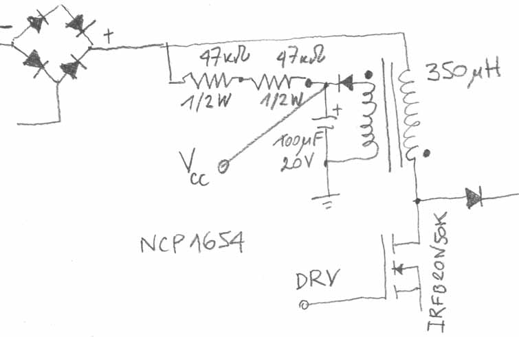
According to the datasheet, the NCP1654 from ON Semniconductors, should be powered by an external power supply +12V to about +20VDC max.
In the application note, they use a +15VDC, but the question is, how powerfull should the external PSU be?
The on-chip driver is capable of delivering +-1,5A and on the schematic of the chip, the Vcc goes directly to the DRV buffer +rail, so I suppose the power supply should be atleast 1,5A@15V, is this correct?
The question is because the datasheet does mention only the chip power consumption but not the load consumption.

Any suggestions about the 15V@2A PSU?
 

This ±1.5 ampere current is Drive Capability of the chip not the consumption, source or sink. The supply capacity depends upon your design. For chip if you see Page4 of the datasheet it says:
NCP1654.jpg
 

yes, this is what the datasheet says, but where the drive current comes from if not from the external power supply?
if you look at the chip schematics, you'll see that the Vcc pin is connected directly to the DRV buffer +rail, that takes me to the decision the drive current comes from the ext.psu
 

your PFC IC has an active current for example 10mA at 100khz.
The MOS or IGBT has a total gate charge for example 70nC.
70nC x 100khz=7mA .so your total current need is 17mA. the 1.5A is the peak capability of the output stage and not the average current.
The average output current dos not depend to Ipeak and is always=Total gate charge X frequency
 
  • Like
Reactions: delwin

    delwin

    Points: 2
    Helpful Answer Positive Rating
things are getting clearer, but dose this means I could feed the +15VDC with a 1/2W 15V zener from the recified mains?

futhermore I recall a thread where somebody has asked, if he could drive the power switch of a motor control in a H-bridge, and the answer was NO, because the driving current is way more than the 555 timer he was going to use can provide, and the 555 can source about 200mA. if only 17mA of current is needed, why we use special power drivers for the mosfet switches in inverter bridges, and not just the output of the opto couplers?

greetings
 

Ok here is an example:
You have a battery 12 volts and capable of delivering 10 amperes but you connect a load of 1 ampere only, will this work ?
Yes the load will draw it's 1 ampere current but capability of the battery is still there as able to supply 10 amperes. Same way, as Mehrshad said in post #4 you need only 7 Ma to drive the stage but the capability of the chip still remains there to be able to supply1.5 amperes.
That is if you want to use (for example) a BJT in output stage, you will need more current to drive the stage, where comes in the capability of the chip. Again your supply capacity will depend upon your stage design that how much current is needed for total circuit.
 

things are getting clearer, but dose this means I could feed the +15VDC with a 1/2W 15V zener from the recified mains?
Sure you can but:
for a 220v main the rectified DC is 290v to 350v .
350 x 20mA =7watt. this is 7% of a 100W SMPS and need a 15 or 20W resistor.....
I have done this for 10mA usage with 3W loss but in a 300W LLC power supply with IRF2153.
 

Hi guys,
Thanks for the information.
I found this solution in the Martie Brown's book.


Do you think this is good solution to the problem?
The PFC is working in CCM, but I think it is not important the mode the controller is working in.

What do you think?
 

yes that looks good because it only feeds to the secondary when the primary boost onductor is discharging into the output cap of the PFC.....that is the right way to do it....because its acting like coupled inductors and not like transformer


if acted like transformer then you need put series impedance to stop current from going too high.

So your sec voltage there will depend on turns ratio and the output voltage

Another way for you is simply to supply the NCP1654 off the main pwm stage auxiliary winding.

There is a yet other way of deriving your pfc ic power from the boost inductor..........i cant remeber now but i think that the ML4821 (I hope i got that right) datasheet has it.

i think also L6562 DATASHEET has app note on pfc ic power supply from the boost inductor aux winding
 

Yes here is demo circuit from L6562. You can compare has almost the same values as you selected fro some other circuit:
Demo.JPG
 

Thank you guys,
I have one more related problem.
I'm calculating the inductor and have some troubles with it.
As the PFC is supposed to be 1200W (400V/3A output) I used the supplied EXCEL tool and got the value for the inductor - L=350uH, IdcMax=10A. The frequency selected is 65kHz.
For the inductor core, I'm going to use E-E ferrites 3C90 from FERROXCUBE.
As I calcuated the needed core size, it shows up that if the core is E42/20/21 set, then I would need about 3,5-4mm air gap, to prevent it from saturation. For the needed 350uH - N=49;AL=147nH;Bmax=308mT;Igap=3,1mm. If I increase a little the airgap, the Bmax would fall to about 280mT and N~51. That would lower the losses in the core, and bring them to about 0,5W/cm3.
Ok, this gap seems way to long.
If I choose E55/28/21, the gap can go down to 1,3mm, but the N=30, is forcing me to use only one turn on the aux.winding that would feed the PFC IC. If I increase the gap, to lower Bmax, as it would be about 330mT(too high for 65kHz), N goes to 35+, and 390V/35turns < 11V per turn, 2turns are >20V and one is not enough. So what do ou suggest?

The question is, does 3-4mm a tremendously long air gap? Is only one turn in the aux winding healthy? What is the reasonable upper limit for an air gap anyway?

Thank you in advance.
 

You can't put 51 turn of proper wire in a EE42 ferrite.
about the aux winding its no problem to make a 20 or 30 v supply and use one resistor and zener.
you will have max 20ma *15v=0.3w loss that is not that much.
 

Status
Not open for further replies.

Similar threads

Part and Inventory Search

Welcome to EDABoard.com

Sponsor

Back
Top