Continue to Site

Welcome to EDAboard.com

Welcome to our site! EDAboard.com is an international Electronics Discussion Forum focused on EDA software, circuits, schematics, books, theory, papers, asic, pld, 8051, DSP, Network, RF, Analog Design, PCB, Service Manuals... and a whole lot more! To participate you need to register. Registration is free. Click here to register now.

Help needed with darkness sensor circuit

Status
Not open for further replies.

rotary

Junior Member level 3
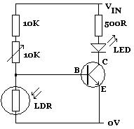
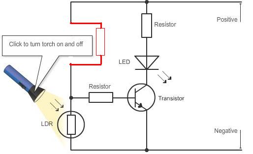
Joined
Oct 10, 2011
Messages
25
Helped
1
Reputation
2
Reaction score
1
Trophy points
1,283
Activity points
1,474
Here's the circuit-

darkness sensor.JPG


It isn't clear to me which part of this circuit makes the voltage divider and also it doesn't show where the voltage output is on the circuit. Can someone tell me those two things please. Also I don't understand why voltage increases as resistance increases in the LDR and why voltage decreases as resistance decreases in the LDR. Can someone explain that too please. It doesn't give an explanation why on this webpage I'm looking at.
 

This may make more sense:

78_1320059948.jpg


John
 

Shouldn't the resistance through the LDR have to be low to allow current to go to the base?
 

You asked for a darkness sensor. I assumed you wanted the LED to come on in darkness. The LDR resistance goes down in light. If you want the LED to come on in light, then do as shown in the first circuit in liteon's link.

John
 

In your schematics, a series resistor is missing.
58_1320063186.jpg
 

What i meant by this thread is I don't understand how the darkness sensor circuit works. I know that light makes the LDR's resistance less but I still don't understand how the circuit works. That is what I was asking for help with understanding. Can someone please explain to me how the circuit works?


And I don't know what you mean about a letter being written by a robot.
 

In the circuit I showed, assume the LDR (call it R2) has a resistance of 400Ω with light and 8,000Ω without light. Ignore the variable resistor for now and just look at the 10,000Ω in series (call it R1) with the LDR to form a voltage divider. The transistor base is connected at the divided voltage (i.e., at the point between the two resistors).

Assume a voltage of 5 V (it can be anything actually). With light, the total resistance of the divider is R1 + R2 (10,400 Ω) and the current is 5V/10,400Ω = 0.5 mA. The voltage across R2 is 0.5 mA X 400Ω = 0.2V. That is not enough base voltage to turn on the transistor, so there is no current between the transistor's collector and emitter. Therefore, the LED stays off.

Now with darkness (i.e., no light), the total resistance is 10,000Ω + 8,000Ω and the current is 5V/18,000Ω = 0.28 mA. The voltage across the LDR (R2) is 0.28 mA X 8,000Ω = 2.2V. That voltage at the base of the transistor is enough to turn it on. It conducts, and the LED is lit.

The variable resistor allows you to set the point at which the light intensity turns the transistor on or off.

You can do the same calculations using real component values from your design.

John
 
The variable resistor allows you to set the point at which the light intensity turns the transistor on or off.
Just to mention transistor turns on when voltage between base and emitter rises above arround 0.6V.
 

Ok thanks guys I will use the information you have given to work out on paper how this circuit works.
 

Status
Not open for further replies.

Part and Inventory Search

Welcome to EDABoard.com

Sponsor

Back
Top