Continue to Site

Welcome to EDAboard.com

Welcome to our site! EDAboard.com is an international Electronics Discussion Forum focused on EDA software, circuits, schematics, books, theory, papers, asic, pld, 8051, DSP, Network, RF, Analog Design, PCB, Service Manuals... and a whole lot more! To participate you need to register. Registration is free. Click here to register now.

[Moved] can anyone help me design a fly back transformer for viper22a

Status
Not open for further replies.

vishnupg

Member level 3
Joined
Dec 24, 2009
Messages
64
Helped
1
Reputation
2
Reaction score
1
Trophy points
1,288
Location
india
Activity points
1,719
can anyone help me design a fly back transformer for viper22a.i have currently designed a powersupply using viper22a.but the efficiency is only 57% so i think i am wrong with transformer because it if for some other viper series. so please help me if anyone has experience designing a powersupply with it.is there any transformers available for this in market
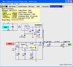
 

You didnt say to much. What power supply You need, DC/AC Inverter? You need 15V on output? ....


At this location You have VIPer calculator, Video Tutorial and FlyBack Designer :

VIPer Design Software
viper53-5volt-1a-flyback-smps.png

STMicroelectronics VIPer Smps Tasar

If there is problem for downloading software contact me.
 
Last edited:

hello there, transformer design is critical for efficiency, and for EMC complinace, we have designed many for tiny sw and viper...
 
I meaned minimum average with load of course (in most cases example: about 80%) if You make this many times.

87% not so bad.
 

okk i will make my requirement clear.i am designing this smps to provide power for a powerline communication board. i will need two secondary output one of 3.3v 1A and other of 16v 0.2a. The efficiency is very important since its going to be industrial product. now as a trial i used some transformer for viper series other than viper22a but i remember both where having switching freq 60khz.so i expected it to work really well. But the max efficiency i am getting is only 57%.this transformer is for 5v/12w so i designed it for 5v and when load is applied to get 1.5 A the voltage drops to 4.8v.

i believe the transformer is the culprit. i am not so experienced with designing transformers and smps.

i tried the link of that software its broken.please give some other link to access it.

thanks to all.
 

Thanks buddy thankyou very much.This is a really tool of ST right. We can Trust this know?
Expecting your cooperation
regards

let me try this out

---------- Post added at 05:54 ---------- Previous post was at 04:49 ----------

hai,
in this software tool i saw primary side regulation and secondary side regulation.i have a good idea about secondary regulation where we take feed back from secondary output and use it to control the pwm of viper.

can anyone explain to me whats primary side regulation and how it works in viper 22a. i saw they use a zener at feed back pin.but couldnt quiet get it working.isnt viper22a a using current feed back
 

Keep in mind your overall efficiency is going to be limited by the 3.3V output. It's rectifier diode will eat up about 13% of the power on that output, so there's really no way to get above 87% without switching topologies or doing something like a synchronous rectifier on the output. Transformer losses should be in the range of 2-5% of your transmitted power for a good design (probably closer to 5% for low power flybacks). So you're almost certainly looking at overall efficiency of less than 80%, probably more like 75%.
 

yes i am expecting above 70% only. As u said if i use a sycnchronous rectifier can i attain a better efficiency. can u please explain a bit. also tell me is the loss in diode due to drop across it
 

Yes, the conduction losses of the diode will be the main issue. Synchronous rectification means that instead of just using a diode as the secondary rectifier, you use a FET which is turned on during the flyback period. The conduction losses of the FET can be much lower than that of the diode it replaces. However for offline isolated converters you need an isolated gate driver, or a gate drive transformer. Also synchronous rectification means that the secondary will always be in continuous conduction mode (unless special control methods are used), which can decrease light load efficiency.

Synchrounous rectification isn't something that's feasible if you want to use a simple controller chip like the topswitch stuff.
 
thanks for your replay.
so i designed a transformer for viper 22a for 5v/8w output.i found that the st software given by tepar wasnt that accurate especially if we change the core size of transformer from the default value the software had choosen.so i studied about transformer design from fairchild application note. and following are turns i obtained.

core EE25
primary:86 turns swg34
aux:13 turns swg34
secon:6 turns swg26 *2

what do you feel.
 

thanks everyone i have now designed a transformer for 3.3v 1.2A
primary 86 turns
aux 13 turns
sec 3 turns

now i also tried winding one output for 16v but the voltage varies greatly especially when 3.3v is loaded..output even goes to 30v on 16v rails.
any suggestions will be helpful
 

if the 16 volt rail has the same 0v as the 3.3 you can use a 13v winding on top of the 3.3 to generate the 16v - this gives better reg on the 16v rail,
also a 15V zener on the added 13v output can limit the volts effectively as long as you are not trying to pull too much power thru the 3.3
 
yes i did try using 13 winding for 16v both are using common ground but the regulation on 16v line is very poor. when 3.3 is loaded to 1 amp voltage on 16 reaches 22.

i dont think we can use zener regulation when i need 16v 200ma output?
 

orson i didnt get exactly what u ment by zener Xtor. is it ordinary zener regulator that we use in the secondary side after putting a resistor.

it may stabilize the voltage but there is no way it deliver 200ma at output
 

ya i too taught about it. but i was doubting weather the temp would rise too high because there will be a drop of 24 volts across ce of transistor and it will be about 5w at 200ma in worst condition.

or else i am thinking of generating 16v .5A from transformer and then using low price efficient DC-DC converter for fixed 3.3 1A output.
if anyone knows good converters at low price without sacrificing efficiency pls post here.

wont it be a better idea when we consider heat and efficiency
 

Status
Not open for further replies.

Part and Inventory Search

Welcome to EDABoard.com

Sponsor

Back
Top