Continue to Site

Welcome to EDAboard.com

Welcome to our site! EDAboard.com is an international Electronics Discussion Forum focused on EDA software, circuits, schematics, books, theory, papers, asic, pld, 8051, DSP, Network, RF, Analog Design, PCB, Service Manuals... and a whole lot more! To participate you need to register. Registration is free. Click here to register now.

How to clip (define) the output signal?

Status
Not open for further replies.
I am checking different options to implement a most stable and reliable CCS; but it is something tricky because the typical ones teached in school and books (using OPAmps), are not the most reliables (because they have "ideal" behaviour) for 'real' purposes.

By the way, when you mean a "band gap", do you mean to replace the Zener by an LDO? How would be this done? (Could you draw a sketch, please? I cannot find any application note about it :shock:)

Thanks!
 
Last edited:

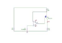
A bandgap reference is like a regulator, except it has very good accuracy specs (initial accuracy, drift, etc.). They are designed for use in high-resolution A/D converters, etc. If you do a search on the web of precision current sources, you'll find a lot of examples. You need to establish how accurate you really need to be, and then analyze the proposed solutions to see if they'll meet your requirements. The simplest solution (one I've used) is this:


Your output is limited to approximately the value of the bandgap voltage (5V in this case). Size your current-setting resistor(R1) or bandgap voltage accordingly.
 
Barry:
Thanks a lot by your help and feedback regarding the band gap!
 

To rely not too much on the stability of the 10V supply, we would preferably connect the reference voltage between +10V and +ve OP input. And use a lower reference voltage, e.g. 2.5 V to achieve the intended output voltage range of the current source. The references are mostly shunt references, so it would be powered by a series resistor from ground, similar to a Z-diode.
 
FvM:
OK, thanks a lot by the remark!
 

FvM is right, using the 10V suppy as a reference is going to impact your accuracy. The schematic I presented was drawn(incorrectly) from memory; my actual circuit used an ADR512 (1.2V) running from a 5V supply. This is not a actually a bandgap, but it has 0.3% accuracy.
 
Barry:
Good! I will keep in mind also, thanks!
 

Status
Not open for further replies.

Similar threads

Part and Inventory Search

Welcome to EDABoard.com

Sponsor

Back
Top