Continue to Site

Welcome to EDAboard.com

Welcome to our site! EDAboard.com is an international Electronics Discussion Forum focused on EDA software, circuits, schematics, books, theory, papers, asic, pld, 8051, DSP, Network, RF, Analog Design, PCB, Service Manuals... and a whole lot more! To participate you need to register. Registration is free. Click here to register now.

[SOLVED] PMOS as voltage divider used in bandgap FAILED on SS and FS corner simulations

Status
Not open for further replies.

allennlowaton

Full Member level 5
Joined
Oct 5, 2009
Messages
247
Helped
3
Reputation
6
Reaction score
3
Trophy points
1,298
Location
Taiwan
Activity points
3,062
Hello EDA fellows,

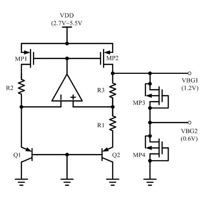
I had used two PMOS that will serve as a voltage divider for the bandgap to produce 1.2V and 0.6V.
I did corner simulations (SS,SF,FS,FF and TT) on the said bandgap and the results went well.
Results for VDD variations (2.7V to 5.5V) and for temperature (-40 to 120deg) are all within an acceptable level.

I connect the bandgap to the rest of the circuit and here now comes the problem.
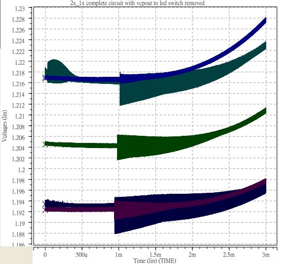
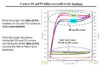
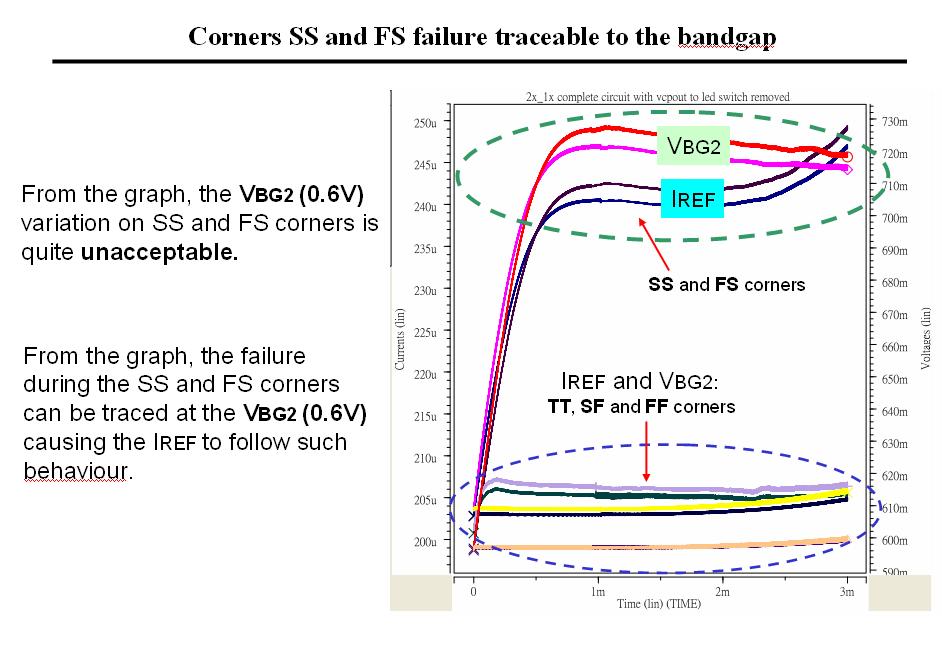
I did a corner on it and the results for SS and FS failed.
TT,SF and FF results are all within an acceptable level.

PMOS device sizes are L=1u , W = 1u and m=4

Below is the simulation results graph.


The IREF in the graph is dependent on the VBG2 (0.6V).
 

Oh. I don't use a start-up for my bandgap.
Anyway, here is the diagram of the bandgap.

91_1311072345.jpg


Although, I didn't include a start-up circuit for the simulation.
I'm wondering why the bandgap fail only at the SS and FS corners?
 
Last edited:

Can I used this start-up circuit for the above bandgap?

15_1311096007.jpg


Does the start-up circuit makes any sense?
 

Hi allennlowaton,

1)Yes… you can use the above start-up circuit to guarantee the proper operation. When VBG1 = 0, the gate of MP1/MP2 will be pulled to ground, what injects current in the bandgap core. When VBG1 achieves 1.2 volts, the start-up will be disconnected to the circuit. Make sure that the voltage divider in the start-up ensures the transistor in the right to be turned off in the proper operation.

2) Regarding your corner simulation… What is the values of VBG1 in the SS corner with and without the voltage divider? Have you tried to increase w/l of MP1/MP2? Are they saturated in these conditions?

Regards
 
I would not expect good ratio tracking on the PMOS FETs
what with different VDS/VGS. But I don't think the issue
pertains to the FET divider (though excessive conductance
would fight the op amp output, perhaps bothering any
natural startup).
 
Hi allennlowaton,

2) Regarding your corner simulation… What is the values of VBG1 in the SS corner with and without the voltage divider? Have you tried to increase w/l of MP1/MP2? Are they saturated in these conditions?

Regards

The VBG1 on SS corner with and without the divider works well during a simulation on the bandgap only (not connected with the other blocks).

Below is the results showing the VBG1 on all corners with voltage divider during a simulation of the bandgap with the rest of the circuit.


The VBG1 on all corners are within an acceptable level.
 

I don't recommend PMOS as voltage divider.
In Slow corner, its vth might be bigger than 0.6V. That will lead to dividing failure.
 
Hi Allennlowaton,

Are you sure that MP2 is in saturation?
There are two different scenarios: (a) with (b) without the voltage divider.
Considering that MP1 and MP2 are equal, in case (a) IMP1 = IMP2. But in (b), these currents are different because the voltage divider.
When IMP2 != IMP1, the VBG1 tends to be increased, when the PTAT voltage across resistor R1 is equal to =UT*ln(A*B). Where A is the ratio size of Q2/Q1, and B is the ratio of currents MP1/MP2.
If the PTAT voltage is higher in case (b), you have less drain-source voltage for MP2, what may cause it to work in linear operation.
Maybe, for corner slow (for PMOS transistor) (does not matter the corner of NMOS), MP2 with higher threshold voltage operates in linear region, since its source-gate voltage is higher for a same current. This is one possible explanation.

Regards.
 
Status
Not open for further replies.

Part and Inventory Search

Welcome to EDABoard.com

Sponsor

Back
Top