Continue to Site

Welcome to EDAboard.com

Welcome to our site! EDAboard.com is an international Electronics Discussion Forum focused on EDA software, circuits, schematics, books, theory, papers, asic, pld, 8051, DSP, Network, RF, Analog Design, PCB, Service Manuals... and a whole lot more! To participate you need to register. Registration is free. Click here to register now.

how to design a taper from rectangular waveguide to circular waveguide using HFSS

Status
Not open for further replies.

yakaya

Newbie level 1
Joined
Jan 25, 2011
Messages
1
Helped
0
Reputation
0
Reaction score
0
Trophy points
1,281
Activity points
1,291
Hello all,
I'm undergraduate student. In my final project, i have to design a taper from rectangular to circular waveguide using HFSS. I'm still newbie to use HFSS. Anyone could help me how to design it directly with HFSS without using AutoCad or VBA?

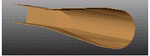
I attach a sample design of smooth taper bellow

Thank you for the attention
 

Attachments

  • TRansitions.gif
    TRansitions.gif
    4.8 KB · Views: 233

Hello,

Well, in HFSS,
- model a box and a cylinder separated by an empty space. This empty space will be the tapered section.
- Then, select the face which have to be connected together (the rectangular one and the circular one)
- Create a new object from this faces
- selected these two sheet and do modeler>surface>connect
et voilà !

You must know define correctly your ports. Pay attention to the fact the the TE11 mode is degenerate.

Hello Hash! This might be an old post, but I'm currently doing this same procedure at the moment. But I'm have no idea in defining the ports correctly for the TE10 of Rectangular and TE11 of Circular. I just used the Integration Lines from the tutorial, but don't know about the circular port. Can anyone explain it to me? Thanks!
 
Hi,

First of all, please read the HFSS documentation:
Technical notes -> Excitationt -> Wave Ports
where you will understand why one may need to enforcement an integration line to a wave port.

Modes are being said degenerate when they have the same cutoff frequency (thus, exciting one mode will excite the other mode).

Then, please read more about circular waveguide, and look in the search engine of this forum. I found for example :
"Generally, most EM software produce a warning in case you have a port which support degenerate modes or multiple modes.
You can separate multiple modes to multiple ports by modifying the number of modes and you can separate degenerate modes by expliciting the mode polarization."

In a circular waveguide, the fundamental mode is TE11. But there is many possible field orientation (and two orthogonal). So you must define your modes orientations using integration lines.

Best regards,

Thanks a lot for your reply! I actually searched the forum for circular waveguide designs and have found lots of related questions about this, but only few responses. Fortunately I found some useful replies, and I think I've managed to make my simulation work now both for HFSS and CST. It is true that I've encountered that same warning stating that there's a mode not included in my time domain calculation (degenerate), not knowing what it means. But after a few readings, I understood now how TE11 circular works. I've just tried remodeling my circular port a while ago using two perpendicular integration lines. So for TE10 rect, only 1 mode; for TE11 cirular, 2 modes (defined explicitly by Int Lines in HFSS and by Polarization angle in CST).

Still, thanks a lot for your reply Hash!
 
Status
Not open for further replies.

Part and Inventory Search

Welcome to EDABoard.com

Sponsor

Back
Top