Continue to Site

Welcome to EDAboard.com

Welcome to our site! EDAboard.com is an international Electronics Discussion Forum focused on EDA software, circuits, schematics, books, theory, papers, asic, pld, 8051, DSP, Network, RF, Analog Design, PCB, Service Manuals... and a whole lot more! To participate you need to register. Registration is free. Click here to register now.

[SOLVED] PIC18F45K20 reset circuit

Status
Not open for further replies.

In2Dusk

Junior Member level 3
Joined
Jul 9, 2011
Messages
31
Helped
0
Reputation
0
Reaction score
0
Trophy points
1,286
Activity points
1,496
PIC18F45K20 reset circuit problem (HELP ME)

I have pic18f45k20 and i can't find how MCLR reset circuit for it should look like.
Only found this circuit:
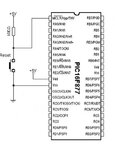
mic-circuit.jpg
Would it work with my chip as well?
What should the resistor value be when my input voltage is 3V?
How to connect it if i am programming it by ICSP using PicKit2?
Will PicKit2 be able to program it when i will be using the same pin it uses?
 

yes you can use this circuit..
the recommended voltage is 5V..
for ICSP program u need the PGM, PGD to be connect..
see the datasheet where is the PGM and PGD pin..
**broken link removed**
 
Re: PIC18F45K20 reset circuit problem (HELP ME)

I have pic18f45k20 and i can't find how MCLR reset circuit for it should look like.
Only found this circuit:
View attachment 58682
Would it work with my chip as well?
What should the resistor value be when my input voltage is 3V?
How to connect it if i am programming it by ICSP using PicKit2?
Will PicKit2 be able to program it when i will be using the same pin it uses?

Hi,

Yes that circuit will be fine with your chip, though it is better to add a 100nf capacitor - see below ..

If you looks at the Pickit2 User Guide, section ICSP Programming, it clearly shows the reset circuitry needed.

The 10k Pull up and other parts will be fine for 3v to 5v and your manual reset switch is just added to the ICSP circuit from the 10k resistor to 0v as before - easy ...
 
Thank you for your posts.
I solved it by connecting Vpp and Mclr together with 20K resistor, and setting power on timer on.
 

Status
Not open for further replies.

Similar threads

Part and Inventory Search

Welcome to EDABoard.com

Sponsor

Back
Top