Continue to Site

Welcome to EDAboard.com

Welcome to our site! EDAboard.com is an international Electronics Discussion Forum focused on EDA software, circuits, schematics, books, theory, papers, asic, pld, 8051, DSP, Network, RF, Analog Design, PCB, Service Manuals... and a whole lot more! To participate you need to register. Registration is free. Click here to register now.

Why is this ckt temperature independent current source?

Status
Not open for further replies.

twlin1

Member level 1
Joined
Nov 3, 2005
Messages
33
Helped
1
Reputation
2
Reaction score
0
Trophy points
1,286
Activity points
1,519
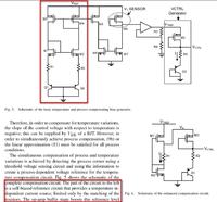
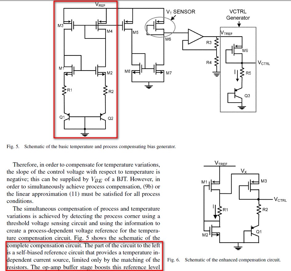
I just read the paper "Process and Temperature Compensation in a 7-MHz CMOS Clock Oscillator" by Krishnakumar Sundaresan. There is a cicuit as attached which is temperature independent current source. But it looks like a PTAT current source in some kind of bandgap structure.Can somebody explain "temperature independent current source" to me? Thanks.
 

Attachments

  • Process and temperature compensation in a 7-MHz CMOS clock oscillator.pdf
    2.4 MB · Views: 131

Hi Twlin1,

I believe the circuit balances the negative temperature coefficient of a VBE against the positive kT/q temperature coefficient of the difference in two VBE's. Specifically, although not shown in the figure, the two pnp devices are likely sized differently. One might be 8 or 10 times the size of the other. When one forces the current in the two to be the same, the difference between the two voltages and series resistors is forced to near zero at the sources of M1 and M2. In a simpler implementation where only R2 is present, the resulting current is, I = VT*ln(N)/R2 where VT is the thermal voltage kT/q and N is the ratio of the area of Q2 to Q1. With two resistors the equation is a bit more complex.

I hope this helps!
 
  • Like
Reactions: twlin1

    twlin1

    Points: 2
    Helpful Answer Positive Rating
Status
Not open for further replies.

Similar threads

Part and Inventory Search

Welcome to EDABoard.com

Sponsor

Back
Top