Continue to Site

Welcome to EDAboard.com

Welcome to our site! EDAboard.com is an international Electronics Discussion Forum focused on EDA software, circuits, schematics, books, theory, papers, asic, pld, 8051, DSP, Network, RF, Analog Design, PCB, Service Manuals... and a whole lot more! To participate you need to register. Registration is free. Click here to register now.

Need help with Vivladi antenna in hfss simulation

Status
Not open for further replies.

LarionUA

Newbie level 3
Joined
May 23, 2010
Messages
3
Helped
2
Reputation
4
Reaction score
2
Trophy points
1,283
Location
Ukraine
Activity points
1,304
Need help with Vivaldi antenna in hfss simulation

I am asking for help.

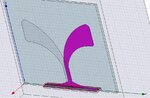
I have made a vivaldi antenna simulation in HFSS v12.0.1

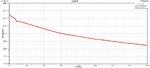
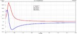
But I have troubles with waveport, and because of this very bad VSWR, S11, real and im impedance parameters...

How should I change my waveport to get normal parameters?

____________________________________________________________
Model of my Vivaldi antenna to download: ww w.edaboard.com/attachment.php?attachmentid=51216&stc=1&d=1291219794


S11 plot: ww w.edaboard.com/attachment.php?attachmentid=51217&stc=1&d=1291219831
____________________________________________________________
P.S. sorry for my english and not normal links, I can't post links until reach 2 posts...
 
Last edited:

When you are defining waveports, renormalize the impedance of the waveport. So the impedance is equal to the characteristic impedance of 50 ohm.
 
Renormalizing changed all characteristics, but not solved the problem.

I will clarify requirements for antenna:
1) stable characteristics on range 3-11 GHz
2) re impedance = ~50 Ohm; im impedance = ~0 Ohm;
3) stable VSWR less then 10 in dB

Below file with my antenna and screens of VSWR, impedances, antenna with port.

And the question: what can be wrong with model, and what should I review and change?..
 

Attachments

  • vivaldi antenna [edit 04.12.10].rar
    56.8 KB · Views: 222
  • 1 - antenna, port.jpg
    1 - antenna, port.jpg
    201.8 KB · Views: 202
  • 2 - VSWR.jpg
    2 - VSWR.jpg
    173.9 KB · Views: 191
  • 3 - re, im impedances.jpg
    3 - re, im impedances.jpg
    196.3 KB · Views: 190
Last edited:
Hey your line in one of teh taper top one is not touching the ground ..it should touch there so as to form proper microstrip line feed..try that and let me know if it helps ...then we will discuss further
 
Hi,

I have corrected your model. See the attached file. This is not vivaldi antenna,it is antipodal vivaldi antenna. you dont need waveport to excite it,instead you need lumped port so that microstrip to feedline transition works properly. As you can see in the VSWR and S11 graph,model is working from 5Ghz to onwards. I havnt optimized the groundplane taper as i do not have time.To enhance bandwidth and go down in freuqency as you mentioned in your previous post play with Groundplane tapering and you will easily get good VSWR which ll cover your required bandwidth i.e 3-11GHz!!! if you have any questions feel free to ask.

/SC
 

Attachments

  • vivaldi antenna [edit 04.12.10].rar
    46.7 KB · Views: 225
Thanks for answers. Its useful.

But now, I'm not working on it already.
 
Status
Not open for further replies.

Part and Inventory Search

Welcome to EDABoard.com

Sponsor

Back
Top