Continue to Site

Welcome to EDAboard.com

Welcome to our site! EDAboard.com is an international Electronics Discussion Forum focused on EDA software, circuits, schematics, books, theory, papers, asic, pld, 8051, DSP, Network, RF, Analog Design, PCB, Service Manuals... and a whole lot more! To participate you need to register. Registration is free. Click here to register now.

[SOLVED] OPtical encoder issue

Status
Not open for further replies.

schneiderj

Newbie level 5
Joined
Jan 17, 2009
Messages
8
Helped
0
Reputation
0
Reaction score
0
Trophy points
1,281
Activity points
1,358
Hello,

I am using an avago encoder to monitor rotation of a gear. My issue is as follow :

140163d1302799025-encodeur-optique-resolution-encodeur-14-04-2011oejpg


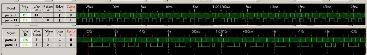
The first record is done at an high rotation speed : we can see that the signal is clean.
Now the second one at low speed : I have many or more transition than expected.

Any idea where is that problem coming from ? And how to solve it ?

Thanks you for your help,
Jean-Marie
 

Please give detail on the encoder
Please give a drawing of the fast and sow signals
 

at slow speed what are the rise and fall times like ? if there is any noise etc you could be getting spurious changes in the middle of a high/low and/or low/high transition. Try putting a Schmitt trigger buffer in the signal lines?
 

Thanks you for your answer.

Encoder is AEDA with 20000 CPR (see datasheet).

klystron > traces are just at the beginning of my message.

at slow speed what are the rise and fall times like ? if there is any noise etc you could be getting spurious changes in the middle of a high/low and/or low/high transition.
I did not measure the fall time and rise time. I will do this afternoon.

As you can seen in the picture of my first message noise occur during after a transition in the middle of a state for example.

I found a note from microchip where they explain there filter used in the dsPIC30F quadrature encoder interface (**broken link removed** page 8. But not such I understand well what they are doing.
If signal is high for 3 cycles, they valid the valu, if not they did not valid it. So the filter is a matter of frequency of Tcy. Is that correct ?

Jean-Marie
 

Attachments

  • AEDA.pdf
    262.2 KB · Views: 90

sounds like you need a schmidt trigger to give some hysteresis to prevent false transitions at low speed
never had problems like this so never changed the QEI filter - may be worth experimenting with it?
 

The simplest way is a redundancy in the optical encoder , for a 12 bit position step use a 13 bits encoder and a software hysteresis , change to next output state by one step only when the reading is higher or lower than current state by two steps and round the output state by one bit. You will have a half step hysteresis.
If you cannot skip the last bit then you can think another workaround based on the fact that the acceleration is limited and at low speeds very quick changes are not possible. For example if the encoder reading changes form n to n+1 in 1 second than just wait for a steady reading of al least 50ms before changing the output state. This is just an example, the optimal delay is given by the maximum acceleration possible in your system
 

Hi,

Here other captures with logic analyzer and oscilloscope.

First one I have 1 second per units of oscilloscope :
**broken link removed**

Second is oscilloscope only with 0.1 second per unit :

**broken link removed**

So it seams Schmidt trigger will not solve this issue. What did you thinks ?

I can't use one bit of encoder to filter encoder status : I need the full resolution (or more... but that an other story).

Your second suggestion mdorian sound interesting. I will take a closer look on it. And at first I have to found a way to be such that I start with a real transition and not a "phantom" one.

Jean-Marie

---------- Post added at 15:51 ---------- Previous post was at 15:22 ----------

Hello again,

I make expected signal more visible in the following picture (or what I thinking the signal is) :

**broken link removed**

Noise could have large interval and acceleration itself is quit large as well : using a windows to filter this signal would be not very efficient at first glance :twisted:...
 

The signal looks very messy but I think that you should check for electromagnetic interferences , check the signal ground of the encoder and use separate ground for signal. I see equally distanced glitches simultaneous on all data lines which might come from the transport motor interfering with the signals.
Do you use differential input?
 
Last edited:
it looks like you have transitions in the middle of the A and B signals at about the same place each period
what happens if the shaft is not moving? does the signal look similar as you change speed until it disappears at high speed?
does the power supply line show anything ?
never seen anything like it! faulty encoder ?
 
From your comments I made several other trial at various rotation speed slow, very slow and more slow than that. Results are :

**broken link removed**

**broken link removed**

Here a rotation speed of 1 rotation in 18 days :
**broken link removed**

And almost no rotation :
**broken link removed**


It seams that what ever the speed is, I have the same pattern. That results, probably, show that this issue is not a problem with the ground (the same ground for motor, microcontroler and encodeur, but all are decoupled with capacitor (10 µ and 100 n).

What are your opinion now ?
Jena-Marie
 

the pattern is fairly regular whatever the speed
it looks to me like a faulty encoder - ask the manufacturers if they have ever seen anyting like it ? try another encoder?
 
the pattern is fairly regular whatever the speed
it looks to me like a faulty encoder - ask the manufacturers if they have ever seen anyting like it ? try another encoder?

Hello,

I follow your recommendation and send a mail to Avago. I did not have an other encoder yet, but will order an other one.

What could be your suggestion knowing that I would like to have :
  • I need about 20 000 cpr
  • but for trial I can lower this resolution to 2000 rpm
  • did not need fats rotation (maw will be 1 rotation per second, but most of the time will be one rotation in 8 minutes)

Jean-Marie
 

Can you spin the encoder by hand without running any power motor to see if the pulses are coming from the motor or from the encoder? It's very unlikely to have a defective encoder but it's possible. Can you show us how the encoder is connected to the main board ? Are you using differential input with DS26C32AM line receiver?
 
Hello mdorian !

encoder is connected to the main board through using differential input with DS26C32AM line receiver to pin rb0 and rb1 of a 18F4520.

I try to spin the encoder manually through the gears, but motor not connected. And all signal are fine but at a quit fast rate, so it is difficult to said something... excepted that my spinning was not continuous ! And during each pulse I am unable to see some "wrong" transition.

After several trials with the motors and playing with intensity I try to change the decay mode from slow to fast one (the driver is a DRV8824 from TI). And surprise the signal is exactly as expected !
I try again the slow decay mode (trace A) and I observe what I had from too long time now... Back to fast decay, again nice signal (trace B). Here are the traces :

**broken link removed**

What does that means ?

And when I am using fast decay the motor make a small noise like "sffffff" !
That the first time I had this noise. Did you know where is that coming from ?

Jean-Marie
 

Hi , look at A signal, I see that your encoder is moving only one degree in 5 seconds , extremely slow and the wheel might have small vibration. I can see a pattern , at -12 second the wheel is making a fast movement back and forth , the upper glitch is wider because the last transition is closer . The same thing is happening at second -9 this time the second signal glitch is wider because it's transition is closer. You can see the same pattern on all glitches, if the transition is closer the glitch is wider. This means that when the motor makes a step the wheel is moving forward and then a small movement backward and forward before stopping.
What can you do?
1 ) use some kind of brake for the wheel at low speed to prevent the oscillation,
2 ) use a motor with smaller steps or a demultiplier between the motor and the wheel.
 
Hello,

I have already a load on the wheel (2 kg) and a worm gear as demultiplier. So I think the only one solution I had is to tun the motor driver to have a better control of the motor steps.

Thanks again for your help
Jean-Marie
 

Status
Not open for further replies.

Similar threads

Part and Inventory Search

Welcome to EDABoard.com

Sponsor

Back
Top