Continue to Site

Welcome to EDAboard.com

Welcome to our site! EDAboard.com is an international Electronics Discussion Forum focused on EDA software, circuits, schematics, books, theory, papers, asic, pld, 8051, DSP, Network, RF, Analog Design, PCB, Service Manuals... and a whole lot more! To participate you need to register. Registration is free. Click here to register now.

TX amp temperature stability

Status
Not open for further replies.

mtwieg

Advanced Member level 6
Joined
Jan 20, 2011
Messages
3,835
Helped
1,310
Reputation
2,626
Reaction score
1,405
Trophy points
1,393
Activity points
29,372
For an experiment I've been running it turns out that the gain of my TX amplifier is drifting as it heats up, and it's throwing off my measurements. I'm seeing the output change by about -2dB as it heats up by about 20 degrees C. I'd like to knock this down to -0.2dB or something close.

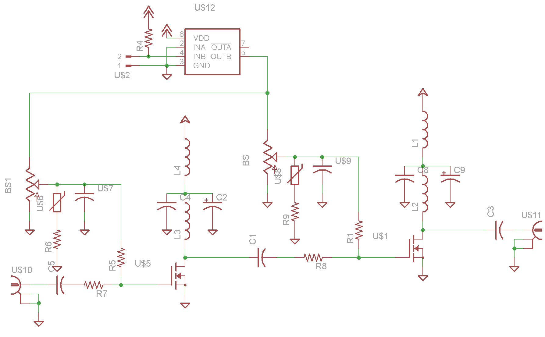
The amplifier is a two stage class A using the MRF136, 64MHz, about 8W max. I'm already using NTCs to put some negative feedback from the transistors to the biasing network, but I think no matter how much I tune it, it'll still drift too much. They're really only there to prevent thermal runaway.

I was looking at DC source degeneration as an option, but I think that I'll need a pretty large resistance (like 10 ohms) to get what I need, so I'm looking at other options, like biasing with a DC current source. But even if I maintain a constant drain bias current, won't my gain still change a bit with temperature?

Also another requirement of my amp is that it must be able to shut down quickly. During a normal experiment I send out 30us bursts of RF every 300us, and the bias is off in between to save power. So any biasing scheme I use would have to have a settling time in the tens of microseconds.

Thanks in advance
 

Some questions..
-Have you ever measured the case temperature at start-up and later on under fully loading condition ??
-In the case of 1, how about drain current ??? What is the deviation from cold state ??
-Does your load has temperature drifting ??
 

Some questions..
-Have you ever measured the case temperature at start-up and later on under fully loading condition ??
I've measured the heatsink temperature with a IR thermometer. It starts around 24 degrees and gets to around 40 degrees within 5 minutes. It seems to be around 42 at stead state.
-In the case of 1, how about drain current ??? What is the deviation from cold state ??
I can see what my power supply is putting out, and it looks like the average quiescent current drops from 160mA to 140mA over time.
-Does your load has temperature drifting ??
I highly doubt it; it's nothing but copper coil with a matching network. Even if it did heat up its electrical properties shouldn't change significantly.
 

I think the problem is not your transistor .. Because from 24 degree to 42 degree can not create a signifcant power drop off..
Other peripheral elements can be reason for instance if you use emitter degeneration resistor, temp. coefficient of these resistors might be wrongly chosen..
Because as I see, the drain current drops off significantly.. Therefore you should focus on the components which can involve into this drop off..
Just in case, you can use PTAT current source that will supply a current proportional to temperature will recover your power..
Can you post your schematic here ??
 

I'm not using any source degeneration with the current version; I just mentioned it as a possibility.
Also keep in mind that I only measured heatsink temp. The die temperature is probably varying by another 15 degrees or so. And both stages are heating up as well, meaning the affect on gain is doubled. That's why I'm sure it's heating in the transistors; there's really no other explanation.

Here's a rough schematic of the amp. There's no impedance matching going on. The bias is fed by a gate driver, which is how the amp is shut off via a logic signal.


I think 160mA Idq is too much for this transistor. Working in Class-A usually the maximum output power should be 25% from the maximum peak power, which for this transistor is 15W. So for Class-A the output power should be about 4W for a normal operation.
Sometimes reducing the Idq and placing the bias in Class-AB can meet almost the same linearity performance as Class-A.

See the applet below to see how the thermal runway in a power MOSFET depends by some parameters.
**broken link removed**
 

I think 160mA Idq is too much for this transistor. Working in Class-A usually the maximum output power should be 25% from the maximum peak power, which for this transistor is 15W. So for Class-A the output power should be about 4W for a normal operation.
Each transistor is rated for 15W out, 55W dissipation. I'm not even close to either of those limits. And the current measurements I gave are for the entire amplifier (that is, both stages together). I've seen these devices pushed far harder than I am.
Sometimes reducing the Idq and placing the bias in Class-AB can meet almost the same linearity performance as Class-A.
That might help temperature drift, but not enough I think. I'll still need something to correct for temperature.
See the applet below to see how the thermal runway in a power MOSFET depends by some parameters.
**broken link removed**
I'm not seeing anything on this page besides the header. Is there some kind of flash plugin or applet I need to view whatever should be there?
 

55W is the maximum rating for the Total Dissipation Power.
Total dissipation power is not the same thing with maximum output power, which is 15W in this case.
You get now 8W output power, which is too much for a Class-A using this transistor.
If you check the application notes for this transistor you will see that the manufacturer recommends Idq between 25mA and 100mA.

The applet link works fine..I think you need Java enabled.
 

55W is the maximum rating for the Total Dissipation Power.
Total dissipation power is not the same thing with maximum output power, which is 15W in this case.
You get now 8W output power, which is too much for a Class-A using this transistor.
No, it's not too much. This exact device is used in tons of class A amplifiers which give 15W peak or more out (the MRF136 is specifically preferred for class A). The average power is much lower, as it is in my application (like maybe 2W average).
If you check the application notes for this transistor you will see that the manufacturer recommends Idq between 25mA and 100mA.
So...? There's no reason it can't work at higher currents and power levels for short durations.
The applet link works fine..I think you need Java enabled.
Thought so. Can't see it on a workstation, I'll try it later at home.
 

How about contant current power source? Even using constant current source, it's also hard to keep power in 0.2dB tolerance.
 

How about contant current power source? Even using constant current source, it's also hard to keep power in 0.2dB tolerance.

So the question I have about constant current biasing is do I need feedback to the gate bias voltage? Fox example say I put some magic current source on my drain (say 150mA), then manually adjust my gate bias until the drain voltage is what I want (around 25V). If the FET heats up, won't the drain bias voltage change a lot, even if gate voltage and drain current are fixed, due to changing transconductance? What I'm worried about it that if the temperature deviates the bias voltage will swing way off, causing large signal distortion on the output.

I was searching online and found the following circuit which uses current feedback from the drain to set the gate voltage:


So is this the kind of current source I need? It's sort of complex, but I'll do it if necessary...
 

The schematic you posted is almost the same as the one from Intersil application note (page 4).

**broken link removed**

They use a microcontroller with stored look-up table inside, which memorize different temperature and bias states.
 
The schematic you posted is almost the same as the one from Intersil application note (page 4).

**broken link removed**

They use a microcontroller with stored look-up table inside, which memorize different temperature and bias states.
Well, I was hoping for a closed loop method that doesn't require extensive measurement and calibration. Also I wonder how they even thermally couple the temp sensor to the transistor. Seems like a little mechanical variation would throw off the temperature reading and screw up the feedback. And I don't have the resources for another serial device (no more I/Os left on my MCU). To clarify, when I said temperature compensation, I wasn't really intent on a circuit that uses temperature as feedback, but still has performance that doesn't depend on temperature. Measuring drain current and using that as feedback seems easier from a design perspective.
 

This is the reason of the look-up table. They do a kind of calibration for each module and store the data in the microcontroller.
Otherwise is true, the temperature sensor (LM35) is very sensitive to small temperature variations (10mV/°C).
Probably this feedback circuit could be designed without microcontroller, but needs some work on tuning the bias at different temperatures.
 

I repeat again here...
I ds drops down to 160mA to 140mA and this current must be compensated by adding Vgs voltage that will be proportional to temperature.The slope of theis voltage will be defined
by cut and try method because you'll never know this slope by model.
The simplest solution is to use PTAT voltage source for Vgs..
 
  • Like
Reactions: mtwieg

    mtwieg

    Points: 2
    Helpful Answer Positive Rating
I used Idd sample with seriesing a vey small resisitor, say 0.1R, and use OpAmp to amplify this voltage difference on this resistor, then compare the voltage with a adjustable negative voltage to close loop, to control Vgs.
But this method have about 2dB error on the output power, that can't meet your requirement.
Yes, this is what I was going to try (though I am going to put the sense resistor on the source, makes the error amp easier to design). But where does your error come from then? The current regulation should be very accurate... or is it that gain still changes with temperature, even if current is fixed?

---------- Post added at 11:10 ---------- Previous post was at 10:56 ----------

I repeat again here...
I ds drops down to 160mA to 140mA and this current must be compensated by adding Vgs voltage that will be proportional to temperature.The slope of theis voltage will be defined
by cut and try method because you'll never know this slope by model.
The simplest solution is to use PTAT voltage source for Vgs..
I should say that the current drops because I do have thermistor feedback in the bias network, and it's apparently too strong. If I used a current sensor, wouldn't it need to be an inverse PTAT (assuming my tempco is positive)?

I went and looked at the datasheet for my device and noticed this:

I didn't know that the tempco of Vgs could be positive... and this implies that there is a certain bias current at which it's equal to zero. Interesting.

Overall I still would like to avoid temperature feedback, mainly because getting a consistent thermal coupling between the transistor and the sensor sounds pretty difficult.
 

From your chart above..
If you decrease VCC so that increase the current, you may catch somehow zero tempco..
The design may be changed slightly but it will be almost temperature independent..
 

I used the closed-loop contant current method with a result of about 20mA~40mA error when Idd=700mA.
My 2dB error is on the spectrum width say about 600M at say 18GHz. So if your freq is fixed point, the result should be better.
I guess the error came from: 5% error on the resistor; OpAmp error; FET error on the whole freq band.
 

So today I built up another, same as the old one, with no temperature compensation or current regulation at all (so Vds and Vgs are fixed). I biased one at about 250mA and the other at 360mA, turned them on, and watched how their operation drifted as temperature rose. I noticed that drain current on the first steadily rose, while the second one (with Id=360mA) was dropping very slightly, so this agrees with the Vgs vs temp curves I posted. However, each Id drifted by only a couple percent, but I noticed much greater changes on my measured S11 and S21. The frequency of my input impedance match steadily drifted up, and my S21 dropped by about 1.5dB. So it looks like drain current isn't the main factor, and the S parameters of the transistors are changing due to temperature alone. What bothers me the most is that my S11 and S21 both dropped, which doesn't seem to make any sense. So I'm not sure what to do now, besides just blindly varying bias conditions until everything balances out and I get a reasonably consistent gain.
 

Status
Not open for further replies.

Part and Inventory Search

Welcome to EDABoard.com

Sponsor

Back
Top