Continue to Site

Welcome to EDAboard.com

Welcome to our site! EDAboard.com is an international Electronics Discussion Forum focused on EDA software, circuits, schematics, books, theory, papers, asic, pld, 8051, DSP, Network, RF, Analog Design, PCB, Service Manuals... and a whole lot more! To participate you need to register. Registration is free. Click here to register now.

TL494 Half Bridge blowing fuse

Status
Not open for further replies.

zeus_threat

Member level 2
Joined
Nov 20, 2010
Messages
45
Helped
2
Reputation
4
Reaction score
2
Trophy points
1,288
Activity points
1,644
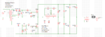
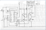
Hi i have built the attached SMPS. I have been able to successfully test it up to 100V with a transformer All waveforms are clean with no ringin or spike. When plugged into 220V the fuse blew up at switch on and both mosfets got shorted GDS. I even added a 0.22R in series with the lower mosfet source and did not measure anything major on low voltages i had to switch the scope to 10 mv range to see a tiny wave form. Any suggestion as to where i could look to sort out the issue? The two 22ohm resistors connected to the main transfo are a pair of 100W lamps that i've used for testing. thanks
 

Attachments

  • Power Section.png
    Power Section.png
    41.4 KB · Views: 289
  • TL494 section.png
    TL494 section.png
    263.9 KB · Views: 528
Last edited:

notice that 22 Ohm resistors are strongly non linear because they're lamps - when they are cold their resistance is much lower compared to the resistance when they're heated.

Also the push-pull transistors if they're slow or not correctly chosen the working point can stay simultaneosly semi opened for short time.
 

Hi thanks for the reply. The 22 ohm are given as a rough figure effectively they will vary with temperature. Do you think the issue is with the Mosfet? I was more thinking towards the voltage applied at start up to the core that could have entered saturation and blow up the mosfet. CAn you please elaborate a little more thanks
 

yes, the start up time is the most critical for the power supply. Did you try to see do you have the same problems if you smootly increase the voltage from 120 to 220V (with some variable autotransformer)? You need to find the conditions in which the transistors blow up, obviously if the schematic works on 120V you need to search for some transition effects.
 

Hi luben thanks for the reply. The only issue is that i don't have such variable supply handy. I only have two 30-0-30V transformer that i swap according to my needs to get 60, 120 and 200V by rewiring secondaries in series or primary back to secondary to get 220V isolated. I am thinking of the following possibilities 1) spikes that appear at the mosfet or 2) The turns ratio on the transformer. I still have 2 pairs of IRF840 handy so i still can do another test. I am thinking of trying the following: check the waveforms of a) GD of each mosfet and b) DS each mosfet c) across the primary from a cold switch on. I did all my measurements after switching on the PSU but not during. Maybe there are some problems occuring in the psu at startup that are within the MOSFET toloerance at 120V but go beyond at 220V. I will also try to get a NTC resistor and add it to protect from startup surge. Its not in the circuit currently. I will post after replacing the mosfet and doing the test.
 

when you measure the signals with oscilloscope ensure that the GND pin of the line connector is not connected to the scope (the GND of the scope should not be galvanically connected to the mains GND). In case you fail to do this you could buy a new scope soon.

If the coil has less turns the currents in the transformer will increase and could probably damage the transistors.
 

Hi Lubben i will take note of the advice you have provided. However in the process I am thinking of making a quick and dirty variable high voltage supply and connect it after the bridge for testing purposes. Maybe the following could be a good starting point : **broken link removed**
but i will need to look further
 

if you go in eBay you can get cheap variable autotransformer. If you plan to build more high voltage applications the variable autotransformer is "must have" equipment. In addition you can galvanically insulate the transformer from the mains by adding one 1:1 transformer (like 220 to 220V, or 110 to 110V). My experience is that without such autotransformer and without galvanic insulation you'll get soon or later problems (it's a kind of russian roulette). By slowly increasing the input voltage you can measure the currents and see the wave forms. Also once the design is ready you need to prove that it works in wide range of voltages - imagine that it's OK on 220V but on 110V it fails. Of course if it's a single hobby task you can make as you like.
 

You may have some problems with your drive circuit.
A quick simulation shows what you should be looking for.
Your one device is still turned on when you turn on the other, causing a short across the supply.

Top trace: drive input
Middle trace: gate voltage
Bottom trace: drain voltage

In the bottom scope display I have added another diode to speed up the turnoff with much better results.
 

Attachments

  • SMPS_drive.gif
    SMPS_drive.gif
    53.6 KB · Views: 160
Last edited:

Hi E-design thanks a lot for the reply. Can you please tell me how the proper trace could be achieved? Sorry i am on a learning curve right now. Did you add resistors to the BD-139, 140 to speed off the turn off sequence? Thanks
 

I just applied a reverse diode from the gate terminal back to the drive winding (S1/S2) to show the difference.
It can be done in several ways. Below is one such way to prevent the risk of accidental dv/dt turn on.
In most cases R1 is left out of the circuit as well.
 

Attachments

  • gate_drive.gif
    gate_drive.gif
    23.7 KB · Views: 171
Last edited:

Hi e-design thanks a lot for the reply. I will implement the scheme you have attached and do some testing. could you please tell me which software you have used to do the simulation?
 

Thanks for the reply E-design I am implementing the gate drive. I will try to sim the power section in one of the above simulator if possible the whole simulator before testing.
 
Hi i got something strange in my waveforms. The low side mosfet signal is good. The high side mosfet signal is good but it has an offset of 10V when measuring bettween Gate and source. Is this normal ?
 
Last edited:
if you are using gate drivers is normal.
 
Hi thanks Kabiru this is my first 220V smps so thats why i am asking these questions. I will go ahead with progressive voltage testing. The unit has already been tested with 30V. With regards to soft start i will try to get a NTC resistor which is missing in my circuit. Do you think using the soft start of the TL494 can be another alternative to using an NTC resistor??? Thanks
 

I've been able to test the circuit on 220V. This time the transformer started to make a buzzing sound and the fuse blew after a minute or so. I am suspecting core staturation or it could be another problem. If i am right about core saturation, which is the easiest way to measure core magnetizing current and to detect the problem?? Thanks
 

you need to put some current probe (or measure voltage on small resistor) to see how currents change with voltage
 

If i may ask,at what frequency are you swiching your mosfet?
 
Status
Not open for further replies.

Part and Inventory Search

Welcome to EDABoard.com

Sponsor

Back
Top