Welcome to our site! EDAboard.com is an international Electronics Discussion Forum focused on EDA software, circuits, schematics, books, theory, papers, asic, pld, 8051, DSP, Network, RF, Analog Design, PCB, Service Manuals... and a whole lot more! To participate you need to register. Registration is free. Click here to register now.
When I try to simulate my current starved VCO with HB simulation how should I test it? I have used a OscPort ,but I am not sure how exactly to get the output.
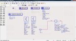
IIRC, you have to connect the OscPort device from the output to the input of the circuit under test. So, rather than having it in-line as a source (which it's not meant to be), you need to have one side tied to port 1 and the other terminal tied to port 2 on your DUT. I believe it worked by evaluating the loop gain of the system... a gain >1 = oscillation.
You also might want to try running your design as a simple transient analysis first... then you can see if it's even starting up . Once you know it'll start and sustain oscillation, then you can move to the HB analysis after tweaking your design to hit your desired frequency of operation.
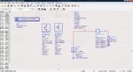
I have tried Transient Analysis I found the oscillations to be sustained .I get my desired center frequency of 400 MHz. I have connected the OSCPort as you have said .Is that correct, because I am still not getting anything at the output.
Double-click on the OscPort object, click the Help button, and read the help file. It tells you exactly where this object needs to be placed in your circuit (generally, inside the feedback loop).
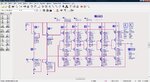
I can't see what's inside your DUT, so I can't be more specific than that.
Double-click on the OscPort object, click the Help button, and read the help file. It tells you exactly where this object needs to be placed in your circuit (generally, inside the feedback loop).
I can't see what's inside your DUT, so I can't be more specific than that.
I'm not familiar with the current-starved oscillator topology, so I probably won't be much help from this point on. All I can tell you is to read up on the OscTest and OscPort component definitions (Help section), and implement them in your circuit accordingly to those directions. Perhaps there is someone on the forum with experience with this particular design. I had to do a balanced oscillator design, using source degeneration for a class project, but that's been my only experience using the OscPort object. I remember that it worked quite nicely, once installed correctly.
You might try putting the proper supply voltages and loads on your DUT, then connecting the OscPort in parallel with your DUT (arrow pointing to the input). It generally needs to be located in the feedback path... perhaps that's all it'd take to get your system to "sing"?
This site uses cookies to help personalise content, tailor your experience and to keep you logged in if you register.
By continuing to use this site, you are consenting to our use of cookies.


")