Continue to Site

Welcome to EDAboard.com

Welcome to our site! EDAboard.com is an international Electronics Discussion Forum focused on EDA software, circuits, schematics, books, theory, papers, asic, pld, 8051, DSP, Network, RF, Analog Design, PCB, Service Manuals... and a whole lot more! To participate you need to register. Registration is free. Click here to register now.

VOLTMETER with PIC 16F877A

Status
Not open for further replies.

alaalwi11

Member level 1
Joined
Nov 30, 2010
Messages
32
Helped
1
Reputation
2
Reaction score
1
Trophy points
1,288
Location
Al khurtum-Sudan
Activity points
1,626
hi friends,
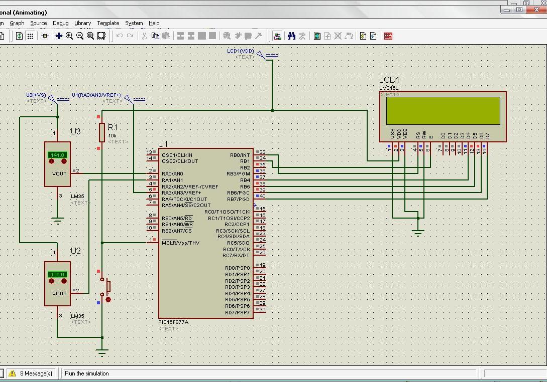
i tried this code for voltmeter but seem there are some errors because there is no text appear in lcd yet ididn't catch it can any one hellp me

Code C - [expand]
1
2
3
4
5
6
7
8
9
10
11
12
13
14
15
16
17
18
19
20
21
22
23
24
25
26
27
28
29
30
31
32
33
34
35
36
37
38
39
40
41
42
//LCD: configuración de pines
sbit lcd_rs at rb2_bit;
sbit lcd_en at rb3_bit;
sbit lcd_d7 at rb7_bit;
sbit lcd_d6 at rb6_bit;
sbit lcd_d5 at rb5_bit;
sbit lcd_d4 at rb4_bit;
//LCD: direccionamiento de pines
sbit lcd_rs_direction at trisb2_bit;
sbit lcd_en_direction at trisb3_bit;
sbit lcd_d7_direction at trisb7_bit;
sbit lcd_d6_direction at trisb6_bit;
sbit lcd_d5_direction at trisb5_bit;
sbit lcd_d4_direction at trisb4_bit;
 
unsigned long adc_value;
unsigned char d1,d2,d3,d4;
 
#define printV     lcd_chr(2,11,48+d1);    lcd_chr_cp(d2+48);                  \
                   lcd_chr_cp('.');        lcd_chr_cp(48+d3);                  \
                   lcd_chr_cp(48+d4);      lcd_chr_cp('V');
                   
#define calcV      d1=adc_value/1000;             d2=(adc_value%1000)/100;     \
                   d3=((adc_Value%1000)%100)/10;  d4=((adc_value%1000)%100)%10;
                   
void main()
{
ADCON1=0b10000010;
TRISA=0XFF;
Lcd_Init();
lcd_cmd(_LCD_CLEAR);
lcd_cmd(_LCD_CURSOR_OFF);
Lcd_Out(1,2,"EVA  PROYECT's");
lcd_out(2,1,"voltage:");
for(;;){
         adc_value=ADC_Read(0);
         adc_value=adc_value*5000/1023;
         calcV
         printV
         delay_ms(20);
        }
}


which compiler you are using?
Lcd_Init();
is it a lib function
 

Hi,
This is mikroC PRO for PIC. I'll have a look after I'm done downloading the trial version of mikroC PRO for PIC.
 
  • Like
Reactions: 4s7ww

    4s7ww

    Points: 2
    Helpful Answer Positive Rating
Thank you for your reply……………
as you say i use mikroC PRO and i hope to solve me problem
Thanks.

Best regards,

alaalwi11
 

Hi,
I've found the mistake. The code is fine. It's the hardware that's the problem. If you look carefully at your code you have specified:
Code:
sbit lcd_rs at rb2_bit;
sbit lcd_en at rb3_bit;
This means RS is connected to RB2 and EN(E) to RB3. But you have connected them to RB0 and RB1 respectively. Just fix that.

I hope you also realize that in hardware, I mean not in Proteus but in real life situation when you'll actually make the circuit, you have to connect a crystal between OSC1 and OSC2 and you can not connect LCD Vee to ground. You should connect it to a pot for contrast adjustment.

You should also know that the code reads from one input only - AN0 not from both AN0 and AN1.

Hope this helps.
Tahmid.
 

Hello every one!!

I want to make milli voltmeter using pic16f877a, which will measure up to 0.001volts.
My code can only measures 0.01volts accurately. Here is the code:

I am using Mikroc.
Please help me.


unsigned char *text,a1,a2,a3,a4,a5;
unsigned long adc_res;

#define print_V lcd_chr(2,11,48+a1); lcd_chr_cp(a2+48); \
lcd_chr_cp('.'); lcd_chr_cp(48+a3); \
lcd_chr_cp(48+a4); lcd_chr_cp(48+a5);

void main()
{
adcon1=0b10000010;
trisa=0xff;
lcd_config(&portb,2,1,0,7,6,5,4); //1,3,2,7,6,5,4);
lcd_cmd(LCD_CURSOR_OFF);
lcd_cmd(LCD_CLEAR);
text= "Milli Voltmeter";
lcd_out(1,2,text);
text="volt";
lcd_out(2,1,text);
for(;;)
{
adc_res=adc_read(0);
adc_res=adc_res*50000/1023;
a1=adc_res/10000;
a2=(adc_res%10000)/1000;
a3=((adc_res%10000)%1000)/100;
a4=(((adc_res%10000)%1000)%100)/10;
a5=(((adc_res%10000)%1000)%10);
print_V;
delay_ms(20);
}
}
 

Hi all
This code from me it work and very stable.
Also the digits has detailed.
:-D
Code:
//PIC16F887
// Clock 20 MHz
// LCD 16x2

int dat = 0;
float volts;
char txt1[6];
char txt2[13];
char *text1 = "ADC=";
char *text2 = "Volt=";

void main()
{
   TRISA = 0xFF;            // PORTA => input
   ANSEL = 0xFF;            // PORTA => Analog
   ADCON1 = 0x00;           // Select Verf and Right Justify
   ADCON0 = 0B11001001;     // Select Analog1 RC_Mode and ADON
   Lcd_Init(&PORTD);
   Lcd_Cmd(LCD_CURSOR_OFF);
   Lcd_Cmd(LCD_CLEAR);
   while(1)
   {
      ADCON0.GO = 1;
      while(ADCON0.GO);
      dat = (ADRESH*4)+(ADRESL/64);
      WordToStr(dat,txt1);
      Lcd_Out(1,1,text1);
      Lcd_Out(1,10,txt1);
      volts = (dat*5)/1023.0;
      FloatToStr(volts,txt2);
      Lcd_Out(2,1,text2);
      Lcd_Out(2,7,txt2);
      Delay_ms(1000);
      Lcd_cmd(LCD_CLEAR);
    }
 }

**broken link removed**
 

Thanks to all for replying me........
And also to boyguitar1.........my lots of problems solved with your code.

Can you plz tell me what relation of voltage divider i have to use when measure voltages in milli volts.
Actually i want to make a voltmeter that will display milli volts on LCD; whichever value of voltage in milli volts given on port A of controller.
 

Hi nudrat,

for voltage devider I just use for adjust inputV to MCU only...
In fact no need to use it.

and for you want display in mV I have change some code as below
Code:
//PIC16F887
// Clock 20 MHz
// LCD 16x2

int dat = 0;
float n = 1023;
float volts;
char txt1[6];
char txt2[13];
char *text1 = "ADC=";
char *text2 = "V=";
char *text3 = "mV=";
char OUT;
void main()
{
   TRISA = 0xFF;            // PORTA => input
   ANSEL = 0xFF;            // PORTA => Analog
   ADCON1 = 0x00;           // Select Verf and Right Justify
   ADCON0 = 0B11001001;     // Select Analog1 RC_Mode and ADON
   Lcd_Init(&PORTD);
   Lcd_Cmd(LCD_CURSOR_OFF);
   Lcd_Cmd(LCD_CLEAR);
   while(1)
   {
      ADCON0.GO = 1;
      while(ADCON0.GO);
      dat = (ADRESH*4)+(ADRESL/64);
      WordToStr(dat,txt1);
      Lcd_Out(1,1,text1);
      Lcd_Out(1,10,txt1);
      volts = (dat*5/n);
      if (dat < 205 ) {volts = (dat*5/1.023); OUT = text3;}else{OUT = text2;}
      FloatToStr(volts,txt2);
      Lcd_Out(2,1,OUT);
      Lcd_Out(2,7,txt2);
      Delay_ms(1000);
      Lcd_cmd(LCD_CLEAR);
      
    }
 }

display in volt (in case of Volt > 1V)
**broken link removed**

display in mV (in case of Volt < 1V)
**broken link removed**


Hope this help :-D
 
Thankuu soooo much boyguitar1!!

It helps me alot..........my all problems almost solved with your code.

Thanks alot.
 

Hi nudrat,

for voltage devider I just use for adjust inputV to MCU only...
In fact no need to use it.

and for you want display in mV I have change some code as below
Code:
//PIC16F887
// Clock 20 MHz
// LCD 16x2

int dat = 0;
float n = 1023;
float volts;
char txt1[6];
char txt2[13];
char *text1 = "ADC=";
char *text2 = "V=";
char *text3 = "mV=";
char OUT;
void main()
{
   TRISA = 0xFF;            // PORTA => input
   ANSEL = 0xFF;            // PORTA => Analog
   ADCON1 = 0x00;           // Select Verf and Right Justify
   ADCON0 = 0B11001001;     // Select Analog1 RC_Mode and ADON
   Lcd_Init(&PORTD);
   Lcd_Cmd(LCD_CURSOR_OFF);
   Lcd_Cmd(LCD_CLEAR);
   while(1)
   {
      ADCON0.GO = 1;
      while(ADCON0.GO);
      dat = (ADRESH*4)+(ADRESL/64);
      WordToStr(dat,txt1);
      Lcd_Out(1,1,text1);
      Lcd_Out(1,10,txt1);
      volts = (dat*5/n);
      if (dat < 205 ) {volts = (dat*5/1.023); OUT = text3;}else{OUT = text2;}
      FloatToStr(volts,txt2);
      Lcd_Out(2,1,OUT);
      Lcd_Out(2,7,txt2);
      Delay_ms(1000);
      Lcd_cmd(LCD_CLEAR);
      
    }
 }

display in volt (in case of Volt > 1V)
**broken link removed**

display in mV (in case of Volt < 1V)
**broken link removed**


Hope this help :-D


can u post hex file
 
ok but with 5v vref how you will get .001 v (1 mv) resolution/ it will be (4.9 mv)
 

How can we change range ?
for example from 0 to 24V ?
 

You need to step the voltage down so that the 24V is within the 5V maximum. Then, you need to use the PIC to calculate the actual voltage depending on the "scaled" (stepped down) voltage.

Hope this helps.
Tahmid.
 

hi everyone good post here. please how can i measure a negative voltage with the pic. for instance i want to measure frm -12 to 0 to 12v
 
Status
Not open for further replies.

Similar threads

Part and Inventory Search

Welcome to EDABoard.com

Sponsor

Back
Top