Fworg64
Junior Member level 2

- Joined
- Mar 23, 2011
- Messages
- 21
- Helped
- 2
- Reputation
- 4
- Reaction score
- 2
- Trophy points
- 1,283
- Location
- North Dakota
- Activity points
- 1,441
I have a DS2E-S-DC1.5V and am wondering if ill break it if i send 6vdc through the coil and/or if it will switch, It says in the data sheet that the max allowable voltage at 50°C is 200% of the Nominal coil voltage (so 3V), but on the next page it says under Rating/Max. switching voltage is 220VDC.
So will it still work with 6V even though its supposed to be used with 1.5V, or will that break it?
I'm not sure if i can link to the datasheet but if you just google "DS2E-S-DC1.5V datasheet" its right there.
So will it still work with 6V even though its supposed to be used with 1.5V, or will that break it?
I'm not sure if i can link to the datasheet but if you just google "DS2E-S-DC1.5V datasheet" its right there.


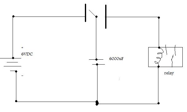
 ). This is my circuit so far...