Continue to Site

Welcome to EDAboard.com

Welcome to our site! EDAboard.com is an international Electronics Discussion Forum focused on EDA software, circuits, schematics, books, theory, papers, asic, pld, 8051, DSP, Network, RF, Analog Design, PCB, Service Manuals... and a whole lot more! To participate you need to register. Registration is free. Click here to register now.

proteus simulation problem

Status
Not open for further replies.

scorrpeio

Full Member level 5
Joined
Dec 26, 2006
Messages
286
Helped
10
Reputation
20
Reaction score
9
Trophy points
1,298
Activity points
3,496
Hi
I am new to Proteus environment.

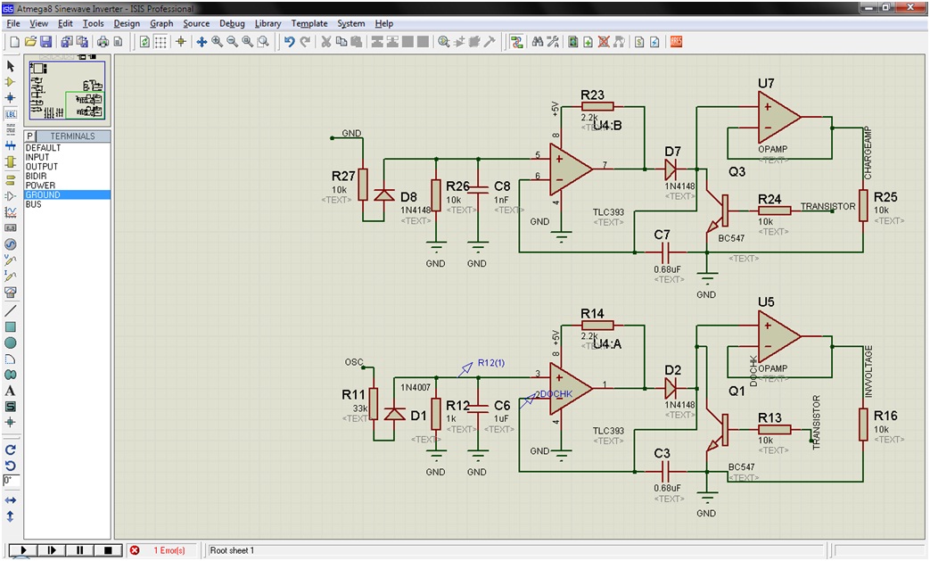
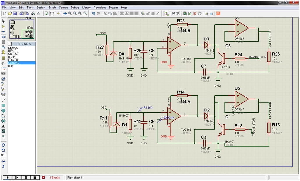
I have created an LED matrix and interfaced it to mc8051 through transistors.
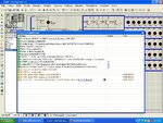
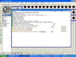
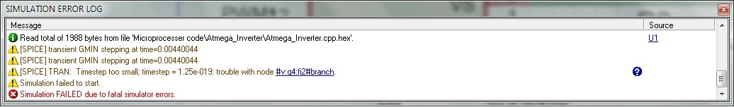
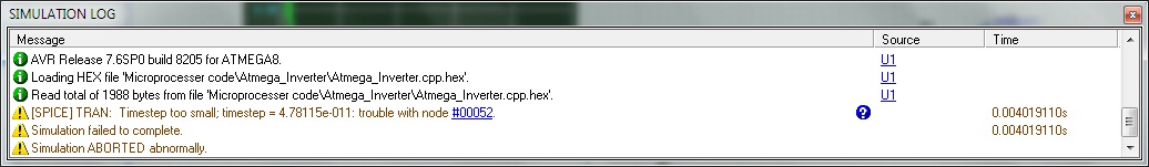
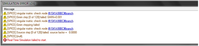
When I simulate it, I am getting following errors(attached image)

Can anyone please tell me, how should I resolve it??? Its since 3 days, I am working on this circuit and still not getting solved :oops:
 

Attachments

  • error message.JPG
    error message.JPG
    189.3 KB · Views: 537

I don't use Proteus and I cannot see your circuit but the error is most likely either a floating node or a circuit configuration which can cause infinite current or voltage e.g. a capacitor across a voltage source with no series resistance. Look carefully at the node referred to in the error message.

Keith
 
Go to system -> set simulation options
there is drop down selector you can select between better convergence and better accuracy, use the first.
If this doesn't work you can further change the simulation parameters manually, go to the iteration tab in the same dialog,
maybe try trapezoid instead of gear, you can also increase the Gmin steps to 200 and ITL4 to 400 (ITL1 and 2 are already set to 1000 and 100 with the previous selection).

Sometimes it may be ground related, check that you have a gnd connected.

Take a look at www.intusoft.com/articles/converg.pdf for more detail for spice convergence problems

Alex
 
  • Like
Reactions: scorrpeio

    scorrpeio

    Points: 2
    Helpful Answer Positive Rating
    V

    Points: 2
    Helpful Answer Positive Rating
Thank you for the replies!!!

Well, I have slightly modified the circuit(attached rar contains the ckt diagram)...
In this ckt diagram, y0-y7 are the outputs of the 74HC138 decoder. The inputs to 74HC138 from 8051 are
p3.5 -> A,
p3.6->B,
p3.7->C


Now, I am getting only one error(attached image)...

Please let me know, how to resolve it...the circuit seems to be okay logically.
 

Attachments

  • D_5.rar
    41.3 KB · Views: 117
  • Error_Msg.JPG
    Error_Msg.JPG
    157.9 KB · Views: 231

It is impossible to tell anything from the circuit. I suggest you track down "#D88 S2#branch". If that doesn't help, start stripping circuitry away to find the problem. It may be a bad model though.

Keith
 
changing the simulation parameters didn't help?
You can upload the circuit if you want so I can check it.

Alex
 

@ alexan_e

I have uploaded the circuit in above post. It is D_5.rar
 

Hi, I meant the proteus project actually so that I can check if I can solve it with different parameters.

Alex
 

Spice simulators need a ground node (node zero usually) AND a DC path to ground from every node. Two capacitors in series will cause a problem. This can usually be solved with a very high resistor from the junction of the two capacitors and ground.

Keith
 

Thanks Keith,

Does this apply to series resistor too ? ( I guess its not so). form your words, I understand that whenever we create a schematic for simulation we should check if all components get ground someway or the other. cause everything is calculated in reference to ground.

I was trying to understand that if my problem too is of similar nature. I get this kind of error. (attached pic file).

and when I click on the node which is posing problem. it says did not find the node.


No, series resistors are OK.

You error node is within Q4 so it may be a bad model. Have a look at the model you are using for Q4.

Another common problem is bad models. Some had discontinuities in them, or values that can shoot off to infinity.

Keith.
 
Hey Keith,

I was about to write back to you . Just then my outlook poped up. saying I got a message from you. :)

as you said about ground problem. I reviewed my circuit for it. I found that I was using IR2112 (mosfet driver) and I connected four mosfets. in full bridge configuration. so thinking its likely that the two high side mosfets might not be getting ground. so i connected a resistor with a value of 10M between ground. and to my astonishment the error disappeared. just to confirm I removed the resistors and the error re appeared.

Keinth Thanks a Million. :)

---------- Post added at 14:30 ---------- Previous post was at 14:09 ----------

Unfortunately my happiness could not last for long. I get another error. I get this error when I connect analog graph. I am attaching the Pic file.


I also got this kind of error...searching on google could get the meaning of the problem...but dont know how to solve it yet.
while working on this error...I was moved to different circuit :( :( :(
 

90% of my time wasted is because of simulation problems. all convergence problems. wish this never exists. :) but no pains no gains.

Well here is my new problem. In the attached word file. It shows the two symmetrical circuit. when i simulate single of it. (deleting other) the simulation goes fine. but when same other is added it gives error.I have put the error in the fig.2 and third shows, the net where the problem exists. it shows in red.
 

Attachments

  • snapshot.zip
    193 KB · Views: 104

I cannot view your document in sufficient detail on my mobile but the most likely problem when combining two identical circuits is having short circuits between the two circuits due to identical node names.

Convergence problems are partly down to the quality of the simulator software and it is not a problem I normally have. If i do get a problem it is usually a bad model.

Keith
 

90% of my time wasted is because of simulation problems. all convergence problems. wish this never exists. :) but no pains no gains.

Well here is my new problem. In the attached word file. It shows the two symmetrical circuit. when i simulate single of it. (deleting other) the simulation goes fine. but when same other is added it gives error.I have put the error in the fig.2 and third shows, the net where the problem exists. it shows in red.

Why don't you simply attach the jpeg image instead of a picture inside a docx inside a zip...
 

Status
Not open for further replies.

Part and Inventory Search

Welcome to EDABoard.com

Sponsor

Back
Top