Continue to Site

Welcome to EDAboard.com

Welcome to our site! EDAboard.com is an international Electronics Discussion Forum focused on EDA software, circuits, schematics, books, theory, papers, asic, pld, 8051, DSP, Network, RF, Analog Design, PCB, Service Manuals... and a whole lot more! To participate you need to register. Registration is free. Click here to register now.

Power switches/mosfets please help

Status
Not open for further replies.
The correct switching method for a 2-switch forward converter is simultaneous switching.
Right.
Rather than using a two-switch forward, if you wish to go down that route, you may be better off doing a single switch forward converter..
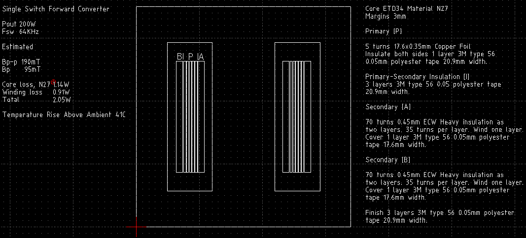
The obvious disadvantage of the 2-switch topology is doubled voltage drop and the need for a floating gate drive. But you shouldn't ignore the respective transformer simplification. I also would prefer push-pull operation, however.

The higher input peak current is probably the most serious argument. But consequently, you won't run the sine modulation on the primary, but use secondary PWM from a DC bus with storage capacitors.

Finally, I won't dwart your suggested concepts, just answer a few questions.
 
Sorry about that. I didn't intend to give the impression I was upset about any 'criticism'. I didn't see it as being that, perhaps I can be a bit off hand at times. Discussing ideas is good.

I understand your preference for the two switch solution in that the natural reset captures leakage inductance energy back to the supply and the transformer is simpler. One thing that has just occurred to me is that if the clamp winding in the single switch version were scaled to allow greater reset voltage then operation above 50% duty would be possible which would reduce current stresses in the circuit. I'm not sure what that would do to the coupling and might not go so far as to suggest a dissipative clamp although it might be worth considering...

Here it is scaled for 80% duty cycle,


In regulation,


Previously,


I suppose it largely comes down to what sort of leakage inductance there will be in the transformer.

Genome.
 

Attachments

  • frwrdb.zip
    1.6 KB · Views: 81
Last edited:
I didn't intend to give the impression I was upset about any 'criticism'.
I wasn't under this impression. I see slightly different preferences, but that's quite normal.

Best regards,
Frank
 
Wow, good discussion. Thanks guys! Thanks for working all that out Genome!

It's somewhat hard for me as a newbie in smps to choose a topology. I originally had decided on a push-pull but when I started working with it I felt that the transformer design was too complicated. That's why I decided to try out the 2-switch forward converter.

The thing is I work for a legitimate company as an engineer (fresh out of school), however I have never designed smps or a transformer, because I studied computer engineering. The transformer will be getting made for me, all I have to do is give the design criteria. I was using the Unitrode/TI "Power Transformer Design", I don't know how to calculate or specify the criteria for a transformer like the one in your forward converter. If you can explain to me how to do that or direct me somewhere then maybe I would be able to move forward with a better solution than a 2-switch forward converter. Unfortunately, there is no one here (where I work) that knows about transformers.

---------- Post added at 10:32 ---------- Previous post was at 10:10 ----------

Before I get the idea that maybe I could design such a transformer with help. How do you guys feel about a RCD reset? Since my input voltage is fairly low, I think it could be a possible solution. A solution by means of a simpler transformer design.

---------- Post added at 10:54 ---------- Previous post was at 10:32 ----------

Another consideration, which I sometimes forget, is that if the transformer design is more complicated then it's going to cost more. I have to make this dirt cheap. So I'm thinking at this point, by deduction using various design/knowledge constraints, that either a 2-switch forward or a single switch forward with RCD reset are my choices. I have spent way too much time just learning about smps and studying topologies. You guys know a lot, I wish I was that knowledgeable about smps and undesirable effects of the different circuits. Therefore, if you only had the option to design it with a single (with RCD reset) or two switch forward converter which would you choose and why? Ha, almost like a short answer test question. Thanks so much!

---------- Post added at 12:29 ---------- Previous post was at 10:54 ----------

I've been trying to get the correct values for the RCD reset circuit... apparently I am doing something wrong. I also discovered another means of resetting the transformer by using an active clamp. One document says its a better choice than the RCD circuit but does require another mosfet. I am going to try it out too.
 
Last edited:

After a bit of further investigation I'm going off the push-pull, although I might have to look at it harder...

For comparison these are the single switch and two switch forwards,


The waveforms as shown are not really meaningful but they look pretty. You'll have to run the analysis and poke about to see what are 'spikes' and what the rest is. I've lost 'faith' in trying to adjust the clamp winding in the single switch one, the clamp diode suffers huge currents. These are both running at 50% duty cycle.

Using an RCD clamp on its own is likely to be a non-starter unless you really really want to throw away some power.

Leakage inductance cripples things basically raising the drive impedance on the secondary so, unless filter inductors are made large or the transformer is wound to produce excess voltage on the output, and stress the diodes, then you can't 'force' the power through.

As a 'fix' I've lowered the winding inductances which would happen with a gapped core but I'm fairly certain that leakage is, to a certain extent, independent of this and in fact may be made worse so my reducing those values in proportion is probably incorrect.

I have included a 'residual' RCD clamp on the single switch version on the assumption that even the primary and clamp windings will not experiece 'perfect' coupling. It wastes 2W.

Overall there is not much to choose in terms of performance. Might as well accept that there will need to be some input filter to make life easier on the battery. The single switch is simpler. I know you do not like 'complex' transformers but as I say the clamp winding comes for 'free' you're winding the primary anyway and it's just a matter of soldering its ends to some pins.

Models attached... off to do some more thinking.

Might I ask what sort of power levels you are looking for?

Genome.

Edit

Might be time to boot up FEMM

Finite Element Method Magnetics: HomePage
 

Attachments

  • forward020311.zip
    3.4 KB · Views: 81
Last edited:
Dang Genome! You yet impress me again. Thanks! This seriously helps me so much. Last week I was really getting stressed out and bummed about this project. You and FvM have lifted my spirits.

the clamp winding comes for 'free' you're winding the primary anyway and it's just a matter of soldering its ends to some pins

Silly me still doesn't get the 'free' winding. Can you please explain it as if it were in "transformers for dummies"? You say it's soldering the ends of the primary to some pins, what pins? The pins of another winding? A solitary winding, separate from the transformer, like an inductor? Or is part of the transformer? I'm sorry, magnetics are still new to me and I'm having a hard time understanding all the different types of transformers. Hence, the desire to have a circuit with the least 'complex' transformer, one that I can comprehend.

Anyway, thanks again! I'm going to 'play' with your circuits now :)

---------- Post added at 10:17 ---------- Previous post was at 10:03 ----------

Might I ask what sort of power levels you are looking for?

The output of the forward converter will be supplying the Vdc bus for the H-bridge which needs to output 200W of power at 110V/60Hz.
 

Since the forward converter is just there to provide the high voltage necessary for 110VAC does it need to have current mode control? I guess what I'm getting at is what needs to be changed in order for your circuit to operate with a H-bridge inverter? Would both the forward converter and the H-bridge operate off of the same PWM controller? Would the forward converter even need a PWM controller?
 

Since the forward converter is just there to provide the high voltage necessary for 110VAC does it need to have current mode control? I guess what I'm getting at is what needs to be changed in order for your circuit to operate with a H-bridge inverter? Would both the forward converter and the H-bridge operate off of the same PWM controller? Would the forward converter even need a PWM controller?

Possibly. I'll leave that concept up to you. Sorry, I have a slight, perhaps misplaced, problem that this is 'commercial use' and I might come up with some 'super whizz' idea for you, which will be seen by others and....

For example, with a bit of work the original 'pure sine' version based on a current fed push-pull may well have been very fruity.

I might be in violation of the FEMM license terms and the results are very dependant on me driving things correctly and interpreting the results. Again I have problems, aside from those licensing terms and I am checking, that I have worked out a method for doing this, nothing guaranteed, and I should just give it away?

At your own risk.

LTSpice, in conjunction with FEMM says,


I haven't included filtering for the battery and would still be bothered what your H-bridge and load would do to things. Otherwise using the RCD clamp results in power losses in R8 of 7.85W

QCAD drawing,


I would be uncertain about regulatory requirements for such devices so I have just assumed 3mm margins for 6mm clearance/creepage.

You will have to decide how to terminate the windings. In the case of the foil primary, which carries high currents, I would note that the bobbin,


Has a notch on the upper circumference and would recommend you use it for flying lead-outs from that particular winding.

It is what it is and as I say it is not necessarily correct but I am not prepared to fiddle about with things to make it, apparently, simpler or 'cheaper'.

QCAD
RibbonSoft
LTSpice
Linear Technology - Design Simulation and Device Models
FEMM
Finite Element Method Magnetics: HomePage

Perhaps I am having a 'bad hair day' but since you have read the Unitrode notes RTFM and work it out. FEMM is, or might be, whizz!

Genome.
 

Attachments

  • bninj050211.zip
    5.9 KB · Views: 80
Thanks Genome! I won't be using any of your exact circuits or transformer designs, so no need to worry about 'commercial use'. However, what you have given to me does help a great deal, so thanks for your time. I still do not have a complete design at this time, but hope to by the end of the week.

Did you use a script to design the transformer in FEMM?
 

Sounds good..

No I did not use any scripting tools although FEMM does come with LUA.[?] I'm a general all around knuckle dragging novice who bends what might be available to produce possibly incorrect results. I've checked with the Author and the license, whilst 'unusual', does not apply to results from the software.

The basic, approximate, core/winding model was produced in QCAD to get a DXF file which FEMM will import. Then I added the various block labels within FEMM. The concepts behind the program are so far above my head as to be almost inconceivable.

Page 41) of the manual under 2.3.11 Block Integrals describes how to determine self and mutual inductances based on what is effectively, to my mind, stored energy. There does not appear to be a 'reasonable' way of extracting 'leakage inductance' or rather one that I would understand. As a result I 'cobbled' one together...

Overall model was,


One winding section..


There are four 'circuits' involved. This one shows C1/C4. The other side uses C2/C3 which are the same magnitude currents but reversed. Those currents are set to 'cancel' according to turns ratios. Ideally you would expect the result would be that no overall energy is stored. The assumption is that any that is measured would be attributable to leakage inductance and therefore indicative of its value..

Setting Circuit 1/2 to 28/-28 Amps and Circuit 3/4 to -1/1 Amps and running the analysis at the expected switching frequency of 64KHz gives.. Pretty Pictures!!!

Flux Density B,


Field Intensity H,


Energy is B X H so you can see the leakage component is sitting between the windings. Red X Red is Exceptionally RED. It is one of the reasons why you sandwich Primary/Secondary or Secondary/Primary.

Doing the block integrals my assumption is that the indicated inductance, based on such energy, is indicative of the leakage inductance associated with that winding..

For the secondary,


Working out the magnitude as SQRT[Re^2 + Im^2] and dividing by 1A^2 gives 823nH.

It is a value I might be wary of and as a result question my methodology. FEMM does give reasonable answers when checking other things and I would not doubt those results using the described methods. In this case since it is me 'guessing' then the results may not be guaranteed.

For the primary,


Working out the magnitude as SQRT[Re^2 + Im^2] and dividing by 28A^2 gives 11.44nH.

FEMM also takes care of skin and proximity effect although once again I might be using it incorrectly. Putting the values so far back into LTSpice and running a transient analysis lets you do an FFT to determine relative contributions.

Slight danger is how you might, or I would expect to, translate from LTSpice results to FEMM. There must be a DC component for which I have used the 'average' value,


Then for the AC components LTSpice plots RMS whilst FEMM uses peak so they need to be converted,


and put back into FEMM for each frequency of interest then summed to get the overall result. I have just used values for the primary current and assumed the secondary will be proportionate according to the turns ratio.


The block integral is for 'Total Losses'.

Regarding core loss I have just calculated a Bpeak excursion and used the manufacturers data sheet graphs to get an approximate value for that based on Bpeak and the switching frequency. I don't doubt FEMM could give something more accurate but then it depends on the driver and the methodology.

Have fun, take care.

Genome.
 
Holy crap Genome! I am going to have to read that about 100x I think. I probably won't do that much analysis. Especially since I was like there's no way I am going to learn how to use FEMM anytime soon. I'd do one heck of a **** job if I tried doing something like what you have done above. Thanks!
 

Genome! Please come back and help me!!!

I have a 2-switch forward converter similar to your "frwrdd" that you provided for me. If the current sensing that you implemented in simulation using "B1= V= I(S1)/40" is replaced with a current sensing resistor, such as a 1mOhm resistor, I experience large turn-on spikes of current up to about 360A. It then levels off to around 30A within about 7ms. However, I can't seem to lower it before then. I even went back to your original circuit to experiment, and I can't get it to go down there either.

Am I doing something wrong or is this a major flaw to the design? I'm assuming that large of a spike would destroy the fets, and I'm not buying a 360A rated fet.

I figure there is a solution but I'm not experienced enough to find it, well I haven't yet anyway.

Please someone help me out. Thanks!
 

Status
Not open for further replies.

Similar threads

Part and Inventory Search

Welcome to EDABoard.com

Sponsor

Back
Top