Continue to Site

Welcome to EDAboard.com

Welcome to our site! EDAboard.com is an international Electronics Discussion Forum focused on EDA software, circuits, schematics, books, theory, papers, asic, pld, 8051, DSP, Network, RF, Analog Design, PCB, Service Manuals... and a whole lot more! To participate you need to register. Registration is free. Click here to register now.

Power switches/mosfets please help

Status
Not open for further replies.

binaryninja

Member level 3
Joined
Nov 11, 2010
Messages
65
Helped
2
Reputation
4
Reaction score
2
Trophy points
1,288
Activity points
1,945
I am working on a DC-AC inverter using a H-bridge. I am trying to select the mosfets I will be using for the hi and lo side switches. Looking for these I have come across "power switches". Considering I am new to smps design these were off my radar.

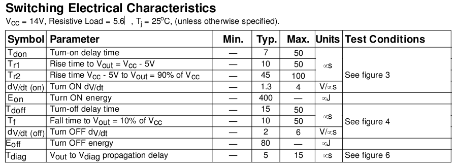
I'm just looking for some clarification on what these are usually used for and why. They appear to just be power mosfets with built in protections and extra pins (that I'm not sure how to use). Here's an example: **broken link removed**

Please provide some insight or explain if you have experience or know. Thanks!
 

Whilst the device comes with a level shift and naturally has the switching times you might associate with a mosfet I have the impression that it is really intended for low frequency 'linear' use rather than within an inverter application.

If I read the description correctly,

The current
limitation is activated until the thermal protection
acts. The over-temperature protection turns off the
high side switch if the junction temperature exceeds
Tshutdown. It will automatically restart after the junc-
tion has cooled 7 oC below Tshutdown.

then the 'current limit' does not turn the device fully off but rather regulates output current at the 5A level until the over-temperature switches the device off properly. As a result I would suggest that the device is not for 'switch mode' use and probably not suitable for your application.

Genome.
 
Whilst the device comes with a level shift and naturally has the switching times you might associate with a mosfet I have the impression that it is really intended for low frequency 'linear' use rather than within an inverter application.
<SNIP>

Genome.

In addition to what Genome mentioned take a look at the switching time. Unless your switching frequency is sub 1kHz these wouldn't work well.


Ray
 
Good analysis... I had overlooked that condition. I automatically went to "well these must be like" instead of actually reading and thinking. Thanks for your time guys!
 
I think my PDF reader may be having problems...

Having suggested mosfets are fast, and they are..


I get.., cut and paste

μs

Ahaaa, so it is Micro-Seconds. You can also see the Turn On and Turn Off energies that result from the limited switching speed.

Tips hat to Rhaynes.
 
ha... yep... I can't even tell what your PDF reader is trying to do... almost looks like an infinity symbol.

Yeah, I want something faster. There are so many freaking MOSFETs available it's hard to pick one. Any suggestions?

The inverter input would be either 12 or 24VDC (haven't decided yet) and it's possible that 20A could go through it. Switching frequency greater than 20kHz. What actually determines the choice of a switching speed?
 

The biggest limit on speed is the gate capacitance which is a function of construction of the FET (different trademark names, TrenchFET, HexFET, etc.), the Gate Threshold (Vgs), and the On Resistance (Rds). Things like lower Vgs increases capacitance but reduces the gate driver requirements. Those kinds of tradeoffs are best put in a spreadsheet and have it calculate results to see what the different tradeoffs are buying or costing you.

I don't know what kind of package you are looking for or what specific electrical parameters you are looking for so I can't suggest one at this point. My favorite search tool is Digikey. It's easy to narrow down the parameters and find real, in stock parts.

Ray


Here is a good write up on gate charge and switching **broken link removed**
 
Last edited:
Thanks! Okay, so basically if the turn-on/off delay times, rise/fall times, and the gate capacitance is low there shouldn't be any problems switching under 1MHz. I'll more than likely be switching between 25kHz and 200kHz.

I also use Digikey for almost all of my electronic needs. The many parameter choices allows for quick narrowing down. Even still there are many to choose from. The packages are where I get all messed up. I think I want to stick with the normal TO-220/2xx package because of heatsink attachment and easier field repair, but the specs on some of the other packages are hard to pass up. Looking at the inverters (car) I have in front of me, they all use the TO-220 package. These are probably the most common because it's been around the longest or it's a price difference, I'm assuming.

Do you think this (Digi-Key - IPP114N03LGIN-ND (Manufacturer - IPP114N03L G)) is a good choice?


For the current you are looking at you will be much closer to 25kHz than 200kHz. As you go higher in frequency the efficiency goes down and at some point goes down very quickly. The trade off is between transformer size and efficiency.


The FET you pointed has reasonably low gate charge, but I worry a little about the voltage. I think it would be fine for a 12V application but not much headroom for 24V input (look for a 40V version). Also you mentioned 20A so you might be shooting for a 200W'ish converter, you'll need to pay attention to efficiency at the FET as slow rise and fall times could put the power dissipation near the 38W limit. Remember that 38W limit is with an infinite heatsink at 25C. But then again in a H bridge I would hope you're not losing more than 5-10W in each leg for a 200W output.

Ray
 
Yes! Everything you said is on the money!

I do wish for 200W of power but this would be at 110VAC. The input to the inverter can have a maximum of 20A, but I don't want 20A on the output, only around 2A.

I do care about efficiency but not as much as I care about price and getting it to work. I also wish to keep the transformer as small as possible, as this would be stepping up the 12 or 24VAC to 110VAC.

You seem proficient in this application. What are your thoughts? Am I in the right ballpark for the mosfet? Except for more voltage headroom. By the way, I am a CPE given the task to design this inverter... I do not have hardly any experience with smps.

Thanks!

[ADDED] : Actually, I don't think that 20A will even make it to the fets in the H-bridge...
 
Last edited:

Ninja,

Most of my converter design experience is with buck converters with only few in the 10-20A range. The FET selection process is very similar. Your choice looks good. There are a lot of FETs in the world but once you start narrowing down the package, voltage, current and on resistance you see a more reasonable number of choices. There may be other issues with inverters that I'm not aware of like. Since a DC/AC switching inverter is really just a rapidly varying bipolar switching power supply, looking at motor control designs maybe a good resource.

Are you familiar with the LT Spice, the Linear Tech simulator? If you don't have to another simulator this would be an excellent choice and it's free. There may already be applicable example circuits in the forum archive.

Ray
 
Yeah, I have LT Spice. It's just that uncomfortable feeling of not being %100 sure. Believe me I have looked and read at many examples, looked at just about every post on here about H-bridge and mosfets. No matter how much I read or look at, I still don't feel confident. Hopefully, I will get there soon.

Thanks for all your help Ray! You're the only person on here who has responded quickly and consecutively since I've joined.
 

What you really would like is a SiC transistor.
The SiC BJTs have switchlosses in order of 500 uJ to 1000 uJ for turn-on and -off.
They can operate easily at 250 degrees (extremly small heatsink)
And they have switching times at around 20 ns, so around 2MHz will keep your volume down.

Just a thought ;)
 
i do had an experience using irf5210..we used these components as an inverter to drive the three phase induction motor control...
 
On a side note. I've never done a line inverter design before and I'm having a problem wrapping my head around how to step this voltage up. I understand how to use the H bridge to create a PWM sinusoidal waveform but how is that voltage raised up. I first thought that the PWM waveform would be passed through a transformer which would be sized based on the PWM frequency but now I believe that won't work. The sinusoidal modulation will cause low frequency currents in the transformer and require the transformer to be sized for the 60Hz not the PWM frequency. Am I thinking of this wrong?

I guess the other approach is to boost the 12VDC to 150VDC and then use a high voltage H bridge to create the 60Hz. That for sure would allow the use of small magnetics.

Ray
 
Going off the top of my head then, based on some of your previous posts, you are looking to make an 'inverter' to convert DC voltage from batteries to AC voltage suitable for mains operated equipment. Without knowing what the 'competition' does, and I have seen some dirt in the past, then the 'classic' step up from a battery via transformer uses a 'push-pull' converter..


LP1, LP2, LS1 and LS2 represent the transformer.

M1 and M2 are driven with 'anti-phase' PWM signals. For an idea have a Google for UC3846 and read what Unitrode/Texas Instruments has to say about them, push-pull converters..

There are various circuits lying about on the intertubes where people leave out LFILT which I would consider to be 'dirt' but each to their own.

Cough..

Given you wish to generate 'high' output voltages, hurts the output diodes and makes the output inductor hard, one of the preferred circuits would/might be a 'current fed push pull'.


Now the 'push-pull' converter is being supplied by a 'buck converter' with the filter inductor on the primary side. The push-pull, M1/M2 gets, slightly, overlapping drive signals with PWM being applied to M3, the buck, in order to control output voltage/current.

You lose the output filter inductor, because it is now at the input, and you can implement a single output winding with a bridge rectifier which will halve the voltage stress on the output diodes. It is more 'complex' and 'may' waste more power but Unitrode/Texas Instruments have a 'solution' in the UC3827...

AC/DC and DC/DC Power Supply - PWM Controller - UC3827-1 - TI.com
**broken link removed**

Thinking 'out of the box' then the loads you might expect to be driving will either be power factor corrected or have their own filtering capacitance in place which might allow you to do this...


Now you have lost the output filter capacitor, relying on the connected load, and rather than having to PWM your bridge to regulate the output you just swap it over at low, 50Hz/60Hz frequency and use the primary side control to give the right answer.

Given the low voltage operation on the primary side you would be looking at low voltage/low RDSon devices for M1-M3. M3 would, ideally, only experience VBATT. M1/M2 would need to suffer twice VBATT plus a 'bit'..

Blah blah blah.. Just floating ideas.

Genome
 
I guess the other approach is to boost the 12VDC to 150VDC and then use a high voltage H bridge to create the 60Hz. That for sure would allow the use of small magnetics.
-I'm trying to prevent this approach where you boost the input to ~180VDC using half-bridge, push-pull, H-bridge, etc then using another H-bridge,etc. to get the 110VAC/60Hz. The reason being is this requires too many fets, especially HV expensive ones.
-Ha... I'm also trying to not use an approach where all these designs on the net that use a large center-tapped transformer (where it's used in reverse from the appliance it was taken out of) where Vbat is input on the center-tap.

Genome, thanks for posting all of that information and ideas... I'm not real knowledgeable when it comes to inverter circuits.

Let me ask you out there this:
1. What is the correct way to design a 12VDC to 110VAC/60Hz inverter?
2. What is the simplest and cheapest way? (besides the center-tapped transformer circuit)

I have sources for a custom transformer. Since this will be a portable design I wish to keep the transformer small, meaning it will have to be a high frequency transformer. I confuse myself easily when I began thinking about switching frequency and transformer frequency. This is taken from a TI/Unitrode power transformer design note:

"Confusion often arises with push-pull topologies.
Think of the push-pull power circuit as a 2:1 frequency
divider, with the transformer and the individual
switches and individual rectifiers operating at a
“transformer frequency”, fT, which is one-half of the
switching frequency. Collectively, the switches and
rectifiers operate at the switching frequency, but the
transformer operates at the transformer frequency.
Some designers define “switching frequency” as the
frequency that the individual switch and the transformer
operate at, but this requires redefining the
term “switching frequency” when dealing with output
ripple and in control loop design."

I thought that I would be able to use PWM to control the switches, that in turn feed the transformer (no center-tap), at their switching frequency, meaning the transformer frequency and switching frequency would be the same. Then on the output of the transformer where the AC voltage would be stepped-up to 110VAC, I could then use a LC filter to get the desired 60Hz. I may be completely off track here, I really don't know. This is harder than I thought it would be. Especially with the design constraints I have been given, which is low, low cost, minimal parts, and small. I want to keep it as simple as possible, I thought I could do it with a PWM controller, two MGD's with both hi and lo (for nmos H-bridge), a hf transformer, LC filter, 4 mosfets, and of course other discretes. Is this not possible?
 

The bad point with doing the sine pwm on the primary (low voltage side) is that you have to design the inverter for double the instantaneous power. Even worse, the battery will have a considerable higher voltage drop and reduced capacity. Capacitive energy storage at th 12 V side would be possible, but capacitors are more bulky than HV types with same energy contents. Considering efficiency, it would be more reasonable to transmit the average DC power and utilize an energy storage and pwm at the HV side.


That is a small cheap 12VDC to 110VAC/60Hz inverter. It employs two KA7500B SMPS (PWM) controllers. You can also see there are 4 fets (w/o heatsink) and 2 fets w/ a heatsink. I'm assuming that the two with the heatsink are a half-bridge converter that probably steps up the 12Vdc to ~180Vdc. Then the 4 fets on the other side are an H-bridge configuration to get the 110VAC/60Hz. Considering there are two KA7500B ICs, one must be controlling the half-bridge and the other controlling the H-bridge. Also note that the transformer (from the pencil/words scale) is quite small.

If you have a different theory then please post it. I need to get this design rolling asap ;)

Thanks!
 

There isn't any filtering except for a LV and HV capacitor, each. Thus I guess, it's rather a square wave than true sine inverter.
 
Status
Not open for further replies.

Similar threads

Part and Inventory Search

Welcome to EDABoard.com

Sponsor

Back
Top