Continue to Site

Welcome to EDAboard.com

Welcome to our site! EDAboard.com is an international Electronics Discussion Forum focused on EDA software, circuits, schematics, books, theory, papers, asic, pld, 8051, DSP, Network, RF, Analog Design, PCB, Service Manuals... and a whole lot more! To participate you need to register. Registration is free. Click here to register now.

Negative coding gain when simulating FEC

Status
Not open for further replies.

byakuya

Junior Member level 3
Joined
Feb 3, 2011
Messages
26
Helped
2
Reputation
4
Reaction score
2
Trophy points
1,283
Activity points
1,442
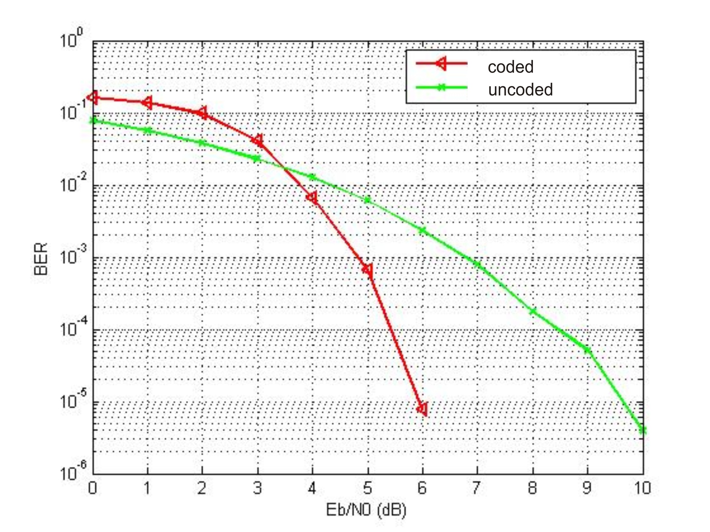
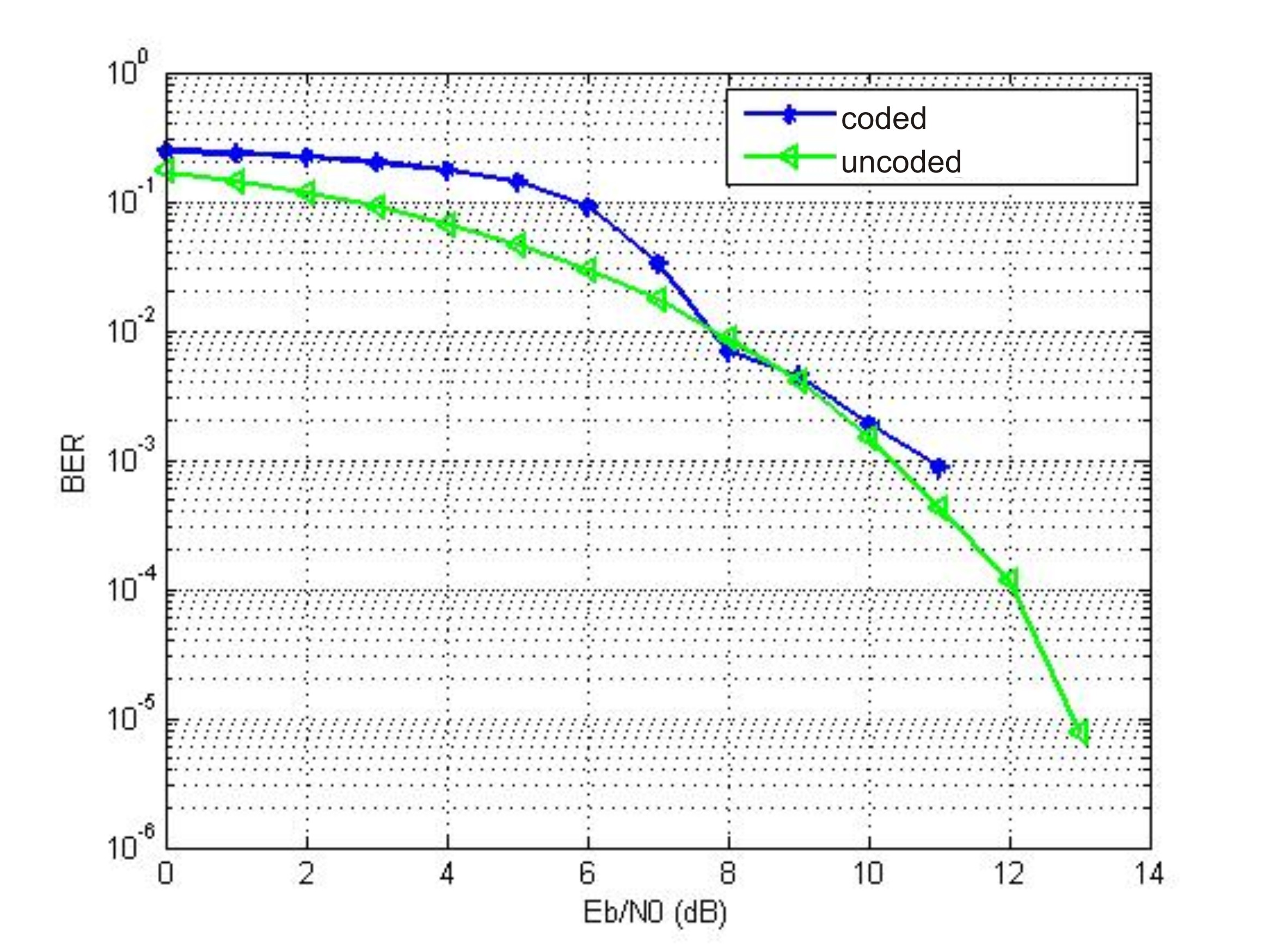
hi, i've tried to simulate FEC and i got negative value when i calculate difference benween uncoded system and coded system ? (maybe i use FEC at unsuitable application)
can i expressed it as coding gain = -X dB?
 

Re: negative coding gain

I've never heard of negative coding gain. I interpret negative coding gain to mean that the Eb/N0 vs. BER of an uncoded signal is better than it's coded counterpart. That shouldn't be the case. A coded signal will have better Eb/N0 vs. BER characteristics than it's uncoded counterpart.
Maybe you are just interpreting (or calculating) your coding gain incorrectly.
 
Re: negative coding gain

Hi,

Normally codes do have negative code gain at high BER (below some Eb/No).
Look at the figure (I've picked up it from the web; i don't guarantee its accuracy, but it is qualitatively coorect).
At BER=1e-5, code gain is about 0.5 dB.
Code gain is 0 dB at BER=0.003, and at BER higher than that, code gain is negative.
Although the (7,4) Hamming code is too simple, for any code the two curves (coded and uncoded) cross at some BER. At that point, the code does not give any advantage. And at lower Eb/No, the coded system is worse than the uncoded one.
But normally this happens at a BER too high, where the system is useless.
Regards

Z
ber_plot_hamming_7_4_code_hard_decode_in_awgn.png
 
i tried for BPSK, QPSK, and 16 QAM. i used regular LDPC 1/2 over AWGN channel.
The result shown bu images respectively for BPSK, QPSK, 16 QAM.
negative coding that i've mentioned before is on 16 QAM, at BER 10^-3


At low SNR, a BPSK symbol with power "3a" would be more immune to noise than three code bits each of power "a", because the noise variance is already high, so it is better to send raw uncoded bits with high power than n code bits each has low power.
 
thank you for all. it's very nice that you response my question :D
yes, i've thought that BPSK and QPSK have better imune to noise. But, My problem is, negative coding when i used 16 QAM , at BER 10^-3.
i got 10,5 dB for uncoded to reach BER 10^-3, but 10,8 dB for coded. So, coding gain is -0,5 dB.
How i expressed this result?
 

Hi byakuya,

Results for BPSK and QPSK look good.
I'm not a specialist in LDPC, but 16QAM results look much worse. I would expect a better performance for Eb/No greater than 8 dB for a reasonable number of iterations.
Yes, the figure shows a coding gain of about -0.5 dB for BER=1e-3. That is the bad point. The 16QAM coded system is practically always worse than the uncoded one.
Regards

Z
 
what do you mean by "The 16QAM coded system is practically always worse than the uncoded one"? why you said that with always?
thank you
regards
 

what do you mean by "The 16QAM coded system is practically always worse than the uncoded one"? why you said that with always?

Because in your third figure, the curve corresponding to coded 16QAM is always at right and above the curve corresponding to the uncoded system.
That means that for a given BER the coded system needs more Eb/No than the uncoded one (negative coding gain). Conversely, for a ginven Eb/No the coded has a greater BER.
Regards

Z
 

what do you think with my result? do you think my 3rd result (regular LDPC with 16 QAM) is wrong?

or maybe, does a system with 16 QAM must use other scheme of LDPC ?
(not regular LDPC)

can anyone explain to me the reason why a got that result for 3rd figure?

thank you
regards
 

Hi byakuya,

Maybe the number of iterations in decoding is not enough?
Have you tried to change it?
Regards

Z
 

i've use 35 times for iteration sir,,, i think it enough for simulation. I've try 50, but it didn't give better performance..

i've tried to find the reason, i found that for 16 QAM system, we should use non binary LDPC. is it right?

what do you think about it?

thank you
 

Hi byakuya,

Maybe the binary case is not optimum with 16QAM, but it should work. (I'm not a specialist in LDPC.)
Isn't there any difference if you increase again the number of iterations?
Regards

Z
 

yes, i got better result, for BPSK and QPSK if i increase iteration, although it should need more time for simulation.

But for binary regular LDPC with 16 QAM, it didn't get better performance if i increase to 50.. (optimum is 35 for 16 QAM, like viewed in figure)
i have tried to simulate 5, 20, 35 and 50 iteration for each modulation type.

regards
 

Status
Not open for further replies.

Part and Inventory Search

Welcome to EDABoard.com

Sponsor

Back
Top