Continue to Site

Welcome to EDAboard.com

Welcome to our site! EDAboard.com is an international Electronics Discussion Forum focused on EDA software, circuits, schematics, books, theory, papers, asic, pld, 8051, DSP, Network, RF, Analog Design, PCB, Service Manuals... and a whole lot more! To participate you need to register. Registration is free. Click here to register now.

GSM Modem not sending any reply to PIC

Status
Not open for further replies.

scorrpeio

Full Member level 5
Joined
Dec 26, 2006
Messages
286
Helped
10
Reputation
20
Reaction score
9
Trophy points
1,298
Activity points
3,496
Hi...

I have interfaced Pulraj GSM modem with PIC18F4520 using UART. I send the command "AT\n\r" to the modem but dont receive "OK" on RX pin of PIC.

I have tested both PIC and Modem individually on hyperterminal.
PIC works absolutely fine...sends AT on hyperterminal and displays the key hit from computer on the LCD.
Modem also works fine with hyperterminal and responds as "OK" when I send "AT" through computer.

Both PIC and Modem are working fine.

I am using the same cable RS232 also. However, it was mentioned in the user document of modem that if 3 wire communication is used, short pin 7 and 8 on the modem and connector.
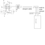
Further, the uart port on the modem side is a female port. I have a rs 232 cable which can be connected between pic and computer properly and also between modem and computer properly.
But, the same wire cant be used as it is between pic and modem. So, I made a 3 wire male to male straight(not crossed) connector and shorted the pin 7 and 8 on the modem side.
Still, Modem is not sending any response on RX pin.

Has anyone faced this problem? What is the solution for it?
 

AT should follow 0x0a and 0x0d as terminating characters....for every command and some use ctrl+Z as terminating cheracter for modems.....

try to use as i have told the terminating characters as 0x0a AND 0X0D..........

other options are

change tx and rx in one side of the serial cable...
 
hi..
I tried changing tx and rx...
in tht case, the last character sent was copied into the RCREG and displayed... I thought it went to loopback form. So, I made straight connection of tx and rx

Also, \n and \r represent the 0x0a and 0x0d. I have already added it.
Still, it is not working.
 

when you change the tx and rx ,,, it will not work with terminal ,, but willl work with the PIC and modem...

sometimes testing cable and interface cable are different
 
Hi,
Check your baud-rate first;
Check voltages used in your Cable for RS232 communication; it must be 0~5V in order to directly interface to a PIC; for PC it may be ±12 V.

If you need very close look at RX,TX lines, use digital-signal-analyzer (Like "Logic tool" facility in Pickit-2 or you can use Parallel-port base logic-analyzer).

Wish you success !
 
hi...
I have tried alll the possible options like changing the RS232 cable, changing TX and RX pin, modifications in the code etc. But still problem is not resolved. I have contacted 1 of my friend who had similar problem. But even after working for more than 2 months he didnt get any solutions, he had to abandon that project.

Is there any issue with PIC18IC and Modem about the compatibility in interfacing?
Has anyone faced this stringent issue?
 

going back to basics.. connect controller board to pc and test it on terminal...
hen program waits for modem response then type ok from terminal and see if program is executing properly
 
I did following tests...

Modem - Hyperterminal :- Worked Fine
PIC - Hyperterminal :- Worked Fine

PIC - Modem :- not working at all


The code I wrote for UART is...

Code:
#include "LCD.h"
#define NULL 0

void SendMessage(char*);
void EnableUART (void);
void DisableUART(void);
void CHEK_isr	(void);
void TX_isr		(void);
void RC_isr		(void);

const char MODEM_SEND[] = "AT\n\r";
static char MODEM_RECV[10];
void main()
{
	signed char cIndex = 1;
	unsigned char  ucResponse[2];
	
	InitialiseDisplay();
	EnableUART();

	while(1)
	{
	}

}

void EnableUART ( void   )
{
	
		TRISCbits.TRISC6   	= 1;	//TX PIN
		TRISCbits.TRISC7   	= 1;	//RX PIN

		SPBRG 			   	= 25;	//BR = 9600
		TXSTAbits.TXEN 	   	= 0;   
		TXSTAbits.BRGH 	   	= 1;
		RCSTAbits.SPEN 	   	= 1;
		RCSTAbits.CREN 	   	= 1;
		BAUDCTLbits.BRG16  	= 0;		
		TXSTAbits.SYNC 	   	= 0;		
		TXSTAbits.TX9  	   	= 0;
		TXSTAbits.TXEN 	   	= 1;

		INTCONbits.PEIE		= 1;    //Enable Peripheral intr 
		PIE1bits.RCIE	 	= 1;	//Enable RX intr
		PIE1bits.TXIE	 	= 1;	//Enable TX intr
		IPR1bits.TXIP		= 0;	//TX - Low Priority intr
		IPR1bits.RCIP		= 0;	//RX - Low Priority intr
		RCONbits.IPEN 		= 1;	//Enable Interrupt Priorities
		INTCONbits.GIEL	   	= 1;	//Enable Low Priority Intr
		INTCONbits.GIE 	   	= 1; 	//Enable interrupts
		
}

void SendMessage( char* Msg)
{

		int len, count = 0;
		TXSTAbits.TXEN 	   = 1;	//Enable UART	  

		while( *(Msg+count) != NULL )
		{
			TXREG = ( *(Msg+count) );    			
			while( !PIR1bits.TXIF )
			{
			 	//Wait till TXREG become empty
			}
			Delay(1);
			count++;
		}	

	TXSTAbits.TXEN = 0;

}

void DisableUART( void   )
{
	TXSTAbits.TXEN = 0;
}

#pragma code low_vector = 0x18
void low_ISR (void)
{
_asm goto CHEK_isr _endasm
}
#pragma code

#pragma interruptlow CHEK_isr

void CHEK_isr(void)
{
	if( PIR1bits.TXIF == 1 )
	{
		TX_isr();
	}
	
	if( PIR1bits.RCIF == 1 )
	{
		RC_isr();
	}

}

void TX_isr(void)
{
	SendMessage(MODEM_SEND);
	TRISB = 0x00;
	PORTB = 0x0A;

}

void RC_isr(void)
{
	TRISB = 0x00;
	PORTB = 0x05;
	MODEM_RECV[0] = RCREG;
	WriteDataToDisplay(MODEM_RECV[0]);
}

Please let me know, how should I proceed to find out the problem.
 

I have attached the circuit diagram of PIC-Modem interface.

The Modem-Hyperterminal interface is same as that of PIC-Modem interface. The only difference is male-male converter. Modem-Hyperterminal communication doesnt need male to male converter. Only straight cable does the job.
 

Attachments

  • pic-modem.JPG
    pic-modem.JPG
    33.9 KB · Views: 145

I have tried with both the way... straight male to male converter and crossed male to male converter. In later case, whatever is transmitted by pic is received on RX pin

---------- Post added at 11:27 ---------- Previous post was at 11:27 ----------

In previous case i.e. straight male to male converter, receive intr is not generated which means nothing is received
 

not really....

Modem works with Hyperterminal
PIC works with hyperterminal

But...

PIC doesnt work with Modem for same set of configuration.
 

Not sure if it will solve your problems, but I wanted to point out that the line terminator should be CRLF (carriage return=0x0D then line feed=0x0A) and is encoded as "\r\n" and not the other way around!

Arthur
 
Hi,

When you connect PIC and Modem, tap TX,RX lines with a logic analyzer (like logic tool in Pickit2) or,
you can connect TX,RX lines to PC com port and activate hyperterminal.

That way you can see what signal is passing on wires. Then you can be more specific on fault.

Thank you,
 
Last edited:
I have checked the TX pin of PIC and T1OUT of Max232. The TX is 0 at reset and goes to 5V while transmission.
The T1OUT is -5 at reset and goes to -9V while transmission.

The Rx pin of PIC is 0 forever.

Is transmission okay?
 

U need to have a software called WindMill Com Debug..
This will help u a lot..
 

Hi,

Could you check voltage of RX pin of modem also ?

You can connect TX,RX of modem to PC com port TX,RX respectively (don't swap) and use a serial-port analyzer tool (like UART-terminal in MikroC or windmill as shafikmirza suggested).

That is the only way to observe what modem received.
 

@DineshSL and @ shafikmirza

I have downloaded the WindMill and checked the data received by Modem while communicating through hyperterminal.
The modem received AT and replied OK.

@ckshivaram

I have connected pull up to the TX and RX pin of PIC. But still there is no response.
When I connected straight cable between pic and modem there is no response from the modem.
When I connected cross cable between pic and modem, the pic receives the same data on RX which is transmitted through TX
 

Status
Not open for further replies.

Similar threads

Part and Inventory Search

Welcome to EDABoard.com

Sponsor

Back
Top