Continue to Site

Welcome to EDAboard.com

Welcome to our site! EDAboard.com is an international Electronics Discussion Forum focused on EDA software, circuits, schematics, books, theory, papers, asic, pld, 8051, DSP, Network, RF, Analog Design, PCB, Service Manuals... and a whole lot more! To participate you need to register. Registration is free. Click here to register now.

circuit protects against ac-line disturbances

Status
Not open for further replies.

joelalfuerto

Junior Member level 3
Joined
Nov 26, 2010
Messages
30
Helped
1
Reputation
2
Reaction score
1
Trophy points
1,298
Activity points
1,463
90_1291950395.png
anyone can help me about the relay in this circuit?

---------- Post added at 16:55 ---------- Previous post was at 16:47 ----------

Here is the simple description of the circuit:
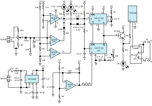
The circuit in Figure 1 protects the ac line against disturbances.
It operates by switching off the power supply upon
detection of undervoltage or overvoltage conditions. The
c i rcuit thus protects refrigerators, washing machines, air
conditioners, and other appliances from permanent damage
that could accrue from working outside their specified
power requirements. The problem assumes particular
importance in underdeveloped countries or regions where
the ac-supply network is incorrectly configured, and the
voltage frequently drops to levels low enough to damage
coils and motors. When the ac-line voltage returns to its
nominal level, the circuit automatically resets a switch and
reconnects the line voltage.
The input stage contains a voltage divider, which you can
adjust with the 1-kV potentiometer. The circuit incorporates
a rectifying diode and a 10-mF storage capacitor that
provides lowpass filtering to stabilize the ac-supply voltagecomparison
level. You should adjust the potentiometer
such that the normal condition of the ac supply, 220V, corresponds
to a 1.97V voltage-comparison level. Three comparison
voltages verify the ac-line status, using resistive
voltage dividers. The voltages correspond to a 10%-undervoltage
warning, a 20%-undervoltage failure level, and a
20%-overvoltage failure level. These comparison voltages
correspond to ac-supply voltages of 198, 176, and 264V,
r e s p e c t i v e l y. Three sections of the quad open-collector
LM339 comparator convert these voltage thresholds to digital
signals.
The 10%-undervoltage warning condition turns on a yellow
LED. Failure conditions turn on a red LED and trigger
the dual retriggerable monostable multivibrator, IC2. The
output of the first ,IC2A, is narrow and serves to define a time
window that prevents sudden transient disturbances from
triggering IC2B. Consequently, if the ac-line voltage quickly
returns to its nominal condition, the circuit does not disconnect
the load. The output pulse width of the other
monostable, which you can adjust via the 50-kV potentiometer,
defines the time the load remains disconnected
after the return of the nominal ac-line voltage.
An RC delay line ensures that when the second monostable
triggers, the first one has already activated its Clear
input. The fourth comparator of the LM339 produces a
high-frequency square wave that continuously retriggers
the monostable while the fault condition is present. To save
power from the regulated 5V supply and to allow use of this
circuit to protect high-current equipment, you should use
an output relay whose coil control comes from the powersupply
rail. A TIC206D triac, gated by the monostable,
switches the relay coil. A green LED indicates that the acline
level is normal and the relay’s contact is closed. IC1, a
Harris HV-2405E offline regulator, supplies the regulated 5V.
Because this circuit connects to the ac line, you should use
an insulated enclosure, and take care in testing the circuit.
 

It is clear from the schematic and the description that the relay is a single pole switch capable of switching mains voltages.
The current capacity of the relay will depend on the load you want to connect to it (that depends on the actual appliances you want to connect and is nothing to do with the circuit you've posted).
The relay's coil appears to be rated at 9 volts DC (but I'm only taking that from the supply voltage shown for the Triac which operates the relay's coil).

Is there something else you wish to know?
 
am i going to put the circuit between the main source and the load?
 

Yes.
The circuit you've posted shows 4 connections to the mains.
Each of these is shown as terminals 'L' and 'N'.
The 2 at the left simply monitor the mains voltage (and only draw a minimal amount of current).
The 2 at the right (the connections to the relay) are where you connect the mains source ('IN') and the appliance load ('OUT').
You will also need to make another connection for the circuit's power supply which isn't included in the schematic. (I can't read the power supply voltages clearly - they look like +5 volts and +9 volts to me).
 
if im going to interface it to a gsm module... is it right that i connect the pin of my microcontroller to comparator indicating overvoltage or on the LED which indicates TOO_HIGH? i am using pic16f877 interface to a GSM module...
 

I don't know the input requirements of the microcontroller, so I can only suggest this as my best guess:
Use the same arrangement on the output of the comparator as already exists on its output for driving the 74HCT123. That is a combination of a diode and a pull-up resistor to the power rail.
 
with regards to the connecti0n at the main in the left side of the circuit, is it only for m0nitoring? How much voltage it draws?
 
with regards to the connecti0n at the main in the left side of the circuit, is it only for m0nitoring? How much voltage it draws?
Yes, it is only connected to the mains for monitoring the voltage.
It draws only about 1 milliAmp (and no voltage drop).

However, please take great care to protect yourself and anyone else from touching the components around that connection, INCLUDING THE VARIABLE RESISTOR. They carry dangerous voltages and should be well insuated.
 
i have a problem in testing the circuit... We d0nt have an hv2405 ofline regulator? Instead of the circuit provided in the diagram.. We change it to a transformer with 7805 regulator but the fuse exploded... Is the ground of the circuit different with the neutral of the main?
 

There has been a recent discussion about the potential difference between Earth & Neutral on the mains supply here.
Yes, the Neutral and Earth may have different voltages. You should check for this with a simple AC voltmeter before experimenting any more.

The 7805 will probably be damaged by now.

In theory, a 7805 should work okay in this application, and it could provide the necessary 5vDC without difficulty. I assume you also used a rectifier and large capacitor on the input to the 7805. What DC voltage do you have across the input of the 7805 ? The problem is probably in your power supply, because its hard to see that any fault downstram from there will draw much current through the fuse.
 
what am i going to do with the ground?
photo.php
what i did in my experiment is i delete the ground of the part with the red box... and the ground of the other came from the regulated 5volts? but what happen is that all the LED is activated... and the same voltage drop is measure at the transistor even i adjust the potentiometer...

---------- Post added at 23:12 ---------- Previous post was at 23:01 ----------

i remove the ground of the voltage divider to the capacitor before it enter the comparator.. and the other ground is dc...
 
Last edited:

Joel.
The "ground" connections in this circuit MUST be connected to the neutral "N" of the mains supply. This is necessary so that the comparator can correctly read the value of the voltage across the L & N terminals.
All the points marked with the "ground" symbol must be connected together and to the Neutral.

Two consequences of this is are:
1. There must be no connection to Earth "E" of the mains supply.
2. The circuit contains potentially dangerous voltages and is a hazard to anyone who may touch any part of the circuit.

The 5volt regulator circuit will be isolated from the mains through the transformer - there will be only ONE connection between the secondary of the power supply transformer and the mains - that will be where you connect the 0v of the power supply to Neutral. No connection to Earth.

Ideally, the whole circuit should be placed in a metal enclosure which is earthed (but isolated from the ground of the circuit).

I hope this helps
 
Last edited:
  • Like
Reactions: joelalfuerto

    V

    Points: 2
    Helpful Answer Positive Rating

    joelalfuerto

    Points: 2
    Helpful Answer Positive Rating
how abou the enclosure of this? What do you think the material i'll be using?
 

The enclosure does not affect the operation of your circuit.
It is for your safety that it is necessary to put the circuit in a metal (conductive) enclosure which is earthed.
You can use aluminium, steel or anything else conductive.

I just don't want anyone building circuits which carry mains voltages being in danger of injury.
 
  • Like
Reactions: joelalfuerto

    V

    Points: 2
    Helpful Answer Positive Rating

    joelalfuerto

    Points: 2
    Helpful Answer Positive Rating
do you think there is no difference d regulated ckt provided in the figure to the usual transformer ckt with regulator 7805.?
 

Joel,
I can't understand your question fully.
There will be no problem if your 5v power supply is built using a transformer, rectifier, capacitors & regulator. But it is important that there is only one connection between the DC side of the transformer to the mains; that will be the connection between the 0v of the PSU and the 'Neutral' of the mains. The only connection to Earth will be to the metal enclosure - this is for your safety.

I hope this helps
 
That depends on what tools you have for testing it!
In our workshop we have an old 'Variac' which is connected to the mains supply and be varied to provide any AC voltage between 0v and 300v.
Perhaps you can borrow a simple petrol generator (with a speed control instead of a regulator), that would provide a range of AC voltages for testing.
Or you could put a high powered light or a small electric heater in series with your circuit, that would provide a low voltage.

When you are ready to start testing, the first thing would be to have an AC meter attached to the mains input so that you have a reference for your observations. You should check the state of the LEDs and the relay, if they behave correctly, then you should check that the 2 time delays work as expected. You should also check the 5volt DC line at all mains voltages - you need a stable 5volt supply at all mains voltages.

But to make a quick start, you could cheat the circuit! Just by adjusting the potentiometer VR1 you can trick it into behaving as if the incoming mains voltage was too high, too low and just normal! That doesn't confirm that the 5volt supply will be okay at all voltages but it will let you confirm most of the other functions.

Hope that helps.
 

i have a problem when i testing it.. the wire from the transformer connected to the wall socket blow up.. what do you think the problem? hope you can help me.. thanks in advance..
 

Joel
Not enough information!

I can't really visualise the circuit around the transformer, sorry. Can you draw it?
If you can draw it, please make sure there are no "hidden" connections - everything between the mains socket and the circuit in post #1 is on the drawing, including the labels on the transformer, exactly what wire 'blew up', and all the earth connections. That might make it clear where the problem is.

Can you disconnect it all from the wall socket and use a meter to see what resistance there is between the earth pin of the plug and any part of your circuit?

If that does not make the fault obvious, then at least we'll know what the circuit looks like for giving you further help.
The next step might be to power up the 5volt power supply alone (everything disconnected from your circuit) - do you have a fuse in the mains supply? There should be one somewhere!
 

Status
Not open for further replies.

Similar threads

Part and Inventory Search

Welcome to EDABoard.com

Sponsor

Back
Top